Specifications (Continued)
■List of supported signals (Y/PB/PR signals)
Signal format | fh(kHz) | fv(Hz) |
480i(525i)@60Hz | 15.73 | 59.94 |
|
|
|
480p(525p)@60Hz | 31.47 | 59.94 |
|
|
|
576i(625i)@50Hz | 15.63 | 50.00 |
576p(625p)@50Hz | 31.25 | 50.00 |
720p(750p)@60Hz | 45.00 | 60.00 |
720p(750p)@50Hz | 37.50 | 50.00 |
1080i(1125i)@60Hz | 33.75 | 60.00 |
1080i(1125i)@50Hz | 28.13 | 50.00 |
1035i(1125i)@60Hz | 33.75 | 60.00 |
1152i(1250i)@50Hz | 31.25 | 50.00 |
■List of supported signals (Video, S-Video signals)
Video mode | fh(kHz) | fv(Hz) | fsc(MHz) |
NTSC | 15.73 | 60 | 3.58 |
PAL | 15.63 | 50 | 4.43 |
SECAM | 15.63 | 50 | 4.25 or 4.41 |
15.73 | 60 | 3.58 | |
15.63 | 50 | 3.58 | |
15.73 | 60 | 4.43 | |
NTSC4.43 | 15.73 | 60 | 4.43 |
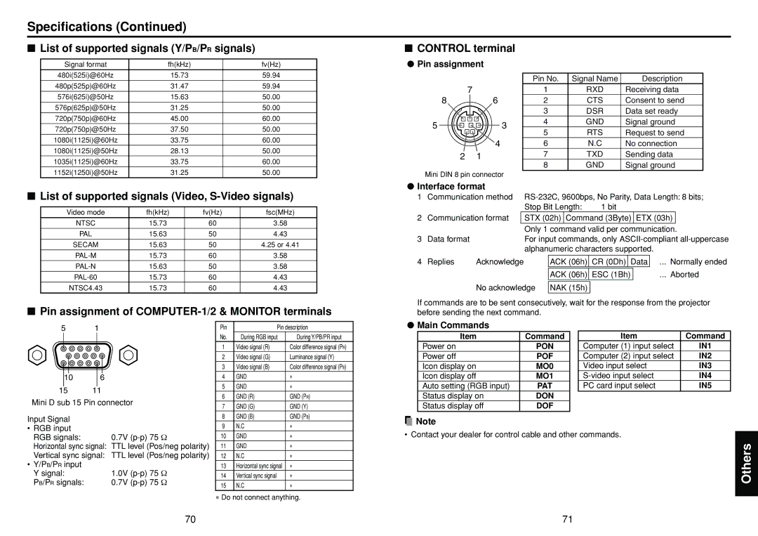
■Pin assignment of
■CONTROL terminal
●Pin assignment
|
|
| Pin No. | Signal Name | Description |
| 7 |
| 1 | RXD | Receiving data |
8 | 6 |
| 2 | CTS | Consent to send |
|
|
| 3 | DSR | Data set ready |
5 |
| 3 | 4 | GND | Signal ground |
| 5 | RTS | Request to send | ||
|
|
| |||
| 4 |
| 6 | N.C | No connection |
2 | 1 |
| 7 | TXD | Sending data |
|
|
| 8 | GND | Signal ground |
Mini DIN 8 pin connector
●Interface format
1 | Communication method | ||||||||||||
|
|
|
| Stop Bit Length: | 1 bit |
|
| ||||||
2 | Communication format |
| STX (02h) | Command (3Byte) | ETX (03h) |
| |||||||
|
|
|
| Only 1 command valid per communication. | |||||||||
3 | Data format |
|
| For input commands, only | |||||||||
|
|
|
| alphanumeric characters supported. |
|
| |||||||
|
|
|
|
|
|
|
|
|
| ||||
4 | Replies | Acknowledge |
| ACK (06h) | CR (0Dh) | Data |
| ... Normally ended | |||||
|
|
|
|
|
|
|
|
| |||||
|
|
|
|
| ACK (06h) | ESC (1Bh) |
| ... Aborted | |||||
|
|
|
|
|
|
|
|
|
|
|
|
|
|
|
| No acknowledge | NAK (15h) |
|
|
|
|
|
|
| |||
If commands are to be sent consecutively, wait for the response from the projector before sending the next command.
5 1
Pin | Pin description |
●Main Commands
106
15 11
Mini D sub 15 Pin connector
No. | During RGB input | During Y/PB/PR input |
1 | Video signal (R) | Color difference signal (PR) |
2 | Video signal (G) | Luminance signal (Y) |
3 | Video signal (B) | Color difference signal (PB) |
4 | GND | ∗ |
5 | GND | ∗ |
6 | GND (R) | GND (PR) |
7 | GND (G) | GND (Y) |
Item | Command |
Power on | PON |
Power off | POF |
Icon display on | MO0 |
Icon display off | MO1 |
Auto setting (RGB input) | PAT |
Status display on | DON |
Status display off | DOF |
Item | Command |
Computer (1) input select | IN1 |
Computer (2) input select | IN2 |
Video input select | IN3 |
IN4 | |
PC card input select | IN5 |
Input Signal |
|
• RGB input |
|
RGB signals: | 0.7V |
Horizontal sync signal: | TTL level (Pos/neg polarity) |
Vertical sync signal: | TTL level (Pos/neg polarity) |
• Y/PB/PR input |
|
Y signal: | 1.0V |
PB/PR signals: | 0.7V |
8 | GND (B) | GND (PB) |
9 | N.C | ∗ |
10 | GND | ∗ |
11 | GND | ∗ |
12 | N.C | ∗ |
13 | Horizontal sync signal | ∗ |
14 | Vertical sync signal | ∗ |
15 | N.C | ∗ |
![]() Note
Note
• Contact your dealer for control cable and other commands.
Others
∗Do not connect anything.
70 | 71 |