LBI-39055
PERSONAL COMPUTERS
In most cases, the Personal Computer (PC) used with the C3 Maestro console is delivered with the Logic Board installed, its hard disk drive formatted and
BOARD SET-UP
IMPORTANT NOTE
Unless otherwise noted, all procedures in this manual should be performed in the order presented.
Hardware
Table 1 lists the PCs approved for use with a C3 Maestro console system. Use of an unapproved computer will void the console system's warranty and support services. Subsequent to the printing of this manual, additional PCs not listed in the table may be approved.
LOGIC BOARD
Normally, the Logic Board is configured correctly and installed inside the PC before the C3 Maestro console system is delivered to the customer. The following information is presented for reference only.
TABLE 1 − APPROVED PERSONAL COMPUTERS
FOR USE WITH THE C3 MAESTRO
DIP Switches
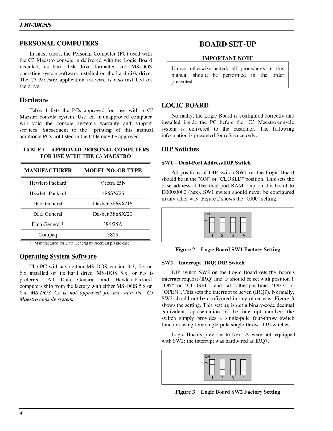
SW1 −
MANUFACTURER
Data General
Data General
Data General*
Compaq
MODEL NO. OR TYPE
Vectra 25N
486SX/25
Dasher 386SX/16
Dasher 386SX/20
386/25A
386S
All positions of DIP switch SW1 on the Logic Board should be in the "ON" or "CLOSED" position. This sets the base address of the
in any other way. Figure 2 shows the "0000" setting. | ||
1 | 23 | 4 |
* Manufactured for Data General by Acer; all plastic case.
Figure 2 − Logic Board SW1 Factory Setting
Operating System Software
The PC will have either
6.x installed on its hard drive.
SW2 − Interrupt (IRQ) DIP Switch
DIP switch SW2 on the Logic Board sets the board's interrupt request (IRQ) line. It should be set with position 1 "ON" or "CLOSED" and all other positions "OFF" or "OPEN". This sets the interrupt to seven (IRQ7). Normally, SW2 should not be configured in any other way. Figure 3 shows the setting. This setting is not a
Logic Boards previous to Rev. A were not equipped with SW2; the interrupt was hardwired as IRQ7.

 123
123


 4
4


Figure 3 − Logic Board SW2 Factory Setting
4