∙Monitor switch input is located at the "B/G PTT" & "MON PTT" terminal block on the I/O Board, at the "FOOTSWITCH 1" female DB-9 connector on the I/O Board, at the "FOOTSWITCH 2" female DB-9 connector on the I/O Board, and at the "DESK MIC" female DB-9 connector on the Audio Matrix Board.
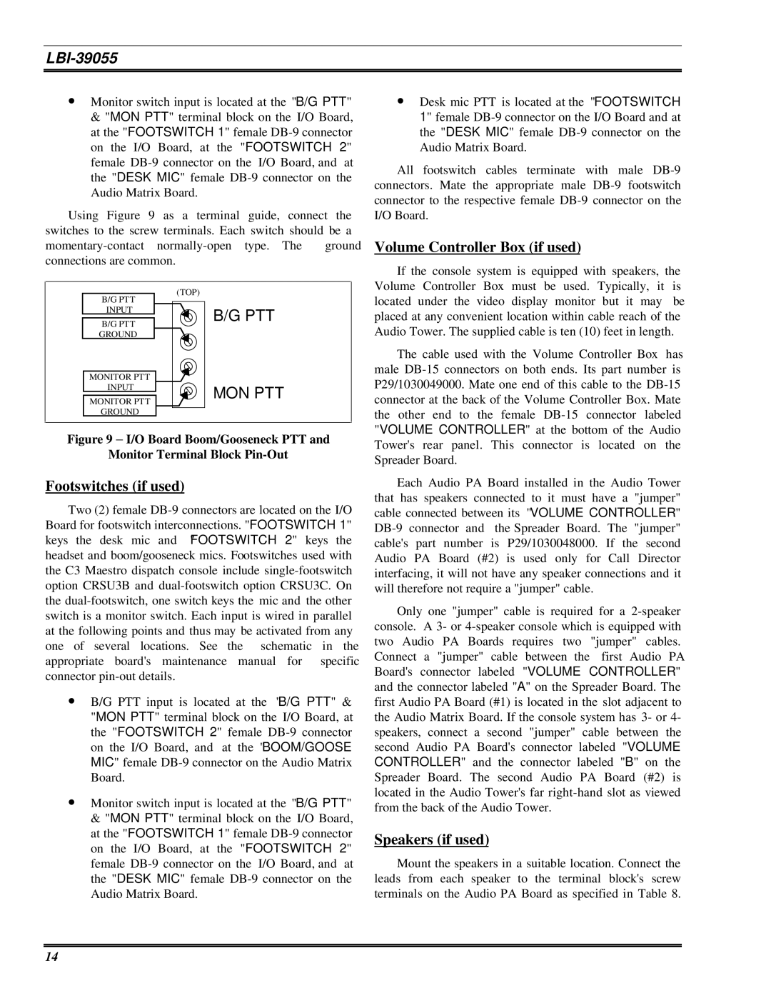
Using Figure 9 as a terminal guide, connect the switches to the screw terminals. Each switch should be a
momentary-contact normally-open type. The ground connections are common.
| B/G PTT | (TOP) |
| |
| INPUT | B/G PTT |
| B/G PTT |
| |
| GROUND | |
| MONITOR PTT | |
| INPUT | MON PTT |
| MONITOR PTT |
| |
| GROUND | |
Figure 9 − I/O Board Boom/Gooseneck PTT and
Monitor Terminal Block Pin-Out
Footswitches (if used)
Two (2) female DB-9 connectors are located on the I/O Board for footswitch interconnections. "FOOTSWITCH 1" keys the desk mic and "FOOTSWITCH 2" keys the headset and boom/gooseneck mics. Footswitches used with the C3 Maestro dispatch console include single-footswitch option CRSU3B and dual-footswitch option CRSU3C. On the dual-footswitch, one switch keys the mic and the other switch is a monitor switch. Each input is wired in parallel at the following points and thus may be activated from any one of several locations. See the schematic in the appropriate board's maintenance manual for specific connector pin-out details.
∙B/G PTT input is located at the "B/G PTT" & "MON PTT" terminal block on the I/O Board, at the "FOOTSWITCH 2" female DB-9 connector on the I/O Board, and at the "BOOM/GOOSE MIC" female DB-9 connector on the Audio Matrix Board.
∙Monitor switch input is located at the "B/G PTT" & "MON PTT" terminal block on the I/O Board, at the "FOOTSWITCH 1" female DB-9 connector on the I/O Board, at the "FOOTSWITCH 2" female DB-9 connector on the I/O Board, and at the "DESK MIC" female DB-9 connector on the Audio Matrix Board.
∙Desk mic PTT is located at the "FOOTSWITCH 1" female DB-9 connector on the I/O Board and at the "DESK MIC" female DB-9 connector on the Audio Matrix Board.
All footswitch cables terminate with male DB-9 connectors. Mate the appropriate male DB-9 footswitch connector to the respective female DB-9 connector on the I/O Board.
Volume Controller Box (if used)
If the console system is equipped with speakers, the Volume Controller Box must be used. Typically, it is located under the video display monitor but it may be placed at any convenient location within cable reach of the Audio Tower. The supplied cable is ten (10) feet in length.
The cable used with the Volume Controller Box has male DB-15 connectors on both ends. Its part number is P29/1030049000. Mate one end of this cable to the DB-15 connector at the back of the Volume Controller Box. Mate the other end to the female DB-15 connector labeled "VOLUME CONTROLLER" at the bottom of the Audio Tower's rear panel. This connector is located on the Spreader Board.
Each Audio PA Board installed in the Audio Tower that has speakers connected to it must have a "jumper" cable connected between its "VOLUME CONTROLLER" DB-9 connector and the Spreader Board. The "jumper" cable's part number is P29/1030048000. If the second Audio PA Board (#2) is used only for Call Director interfacing, it will not have any speaker connections and it will therefore not require a "jumper" cable.
Only one "jumper" cable is required for a 2-speaker console. A 3- or 4-speaker console which is equipped with two Audio PA Boards requires two "jumper" cables. Connect a "jumper" cable between the first Audio PA Board's connector labeled "VOLUME CONTROLLER" and the connector labeled "A" on the Spreader Board. The first Audio PA Board (#1) is located in the slot adjacent to the Audio Matrix Board. If the console system has 3- or 4- speakers, connect a second "jumper" cable between the second Audio PA Board's connector labeled "VOLUME CONTROLLER" and the connector labeled "B" on the Spreader Board. The second Audio PA Board (#2) is located in the Audio Tower's far right-hand slot as viewed from the back of the Audio Tower.
Speakers (if used)
Mount the speakers in a suitable location. Connect the leads from each speaker to the terminal block's screw terminals on the Audio PA Board as specified in Table 8.