IMPORTANT SAFEGUARDS continued
E1 MANUAL
2TABLE OF CONTENTS
items placed upon or against them, paying particular atten- tion to cords at plugs, convenience receptacles, and the point where they exit from the product.
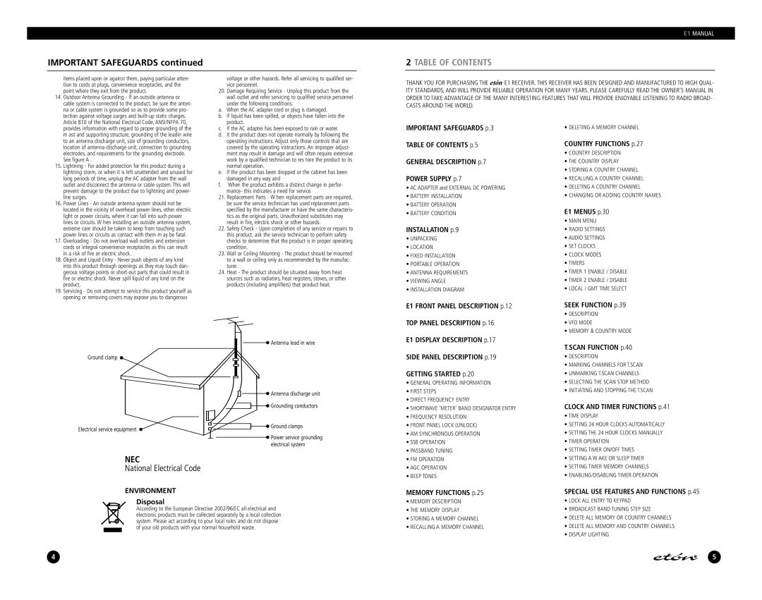
14. Outdoor Antenna Grounding - If an outside antenna or |
cable system is connected to the product, be sure the anten- |
na or cable system is grounded so as to provide some pro- |
tection against voltage surges and |
Article 810 of the National Electrical Code, ANSI/NFPA 70, |
voltage or other hazards. Refer all servicing to qualified ser- vice personnel.
20.Damage Requiring Service - Unplug this product from the wall outlet and refer servicing to qualified service personnel under the following conditions:
a. | When the AC adapter cord or plug is damaged. |
b. | If liquid has been spilled, or objects have fallen into the |
| product. |
THANK YOU FOR PURCHASING THE etón E1 RECEIVER. THIS RECEIVER HAS BEEN DESIGNED AND MANUFACTURED TO HIGH QUAL-
ITY STANDARDS, AND WILL PROVIDE RELIABLE OPERATION FOR MANY YEARS. PLEASE CAREFULLY READ THE OWNER’S MANUAL IN ORDER TO TAKE ADVANTAGE OF THE MANY INTERESTING FEATURES THAT WILL PROVIDE ENJOYABLE LISTENING TO RADIO BROAD- CASTS AROUND THE WORLD.
provides information with regard to proper grounding of the |
m ast and supporting structure, grounding of the leadin wire |
to an antenna discharge unit, size of grounding conductors, |
location of |
electrodes, and requirements for the grounding electrode. |
See figure A . |
15. Lightning - For added protection for this product during a |
lightning storm, or when it is left unattended and unused for |
long periods of time, unplug the AC adapter from the wall |
outlet and disconnect the antenna or cable system. This will |
prevent damage to the product due to lightning and power- |
line surges. |
16. Power Lines - An outside antenna system should not be |
located in the vicinity of overhead power lines, other electric |
light or power circuits, where it can fall into such power |
lines or circuits. W hen installing an outside antenna system, |
extreme care should be taken to keep from touching such |
power lines or circuits as contact with them m ay be fatal. |
17. Overloading - Do not overload wall outlets and extension |
cords or integral convenience receptacles as this can result |
in a risk of fire or electric shock. |
18. Object and Liquid Entry - Never push objects of any kind |
into this product through openings as they may touch dan- |
gerous voltage points or |
fire or electric shock. Never spill liquid of any kind on the |
product. |
19. Servicing - Do not attempt to service this product yourself as |
opening or removing covers may expose you to dangerous |
c. | If the AC adapter has been exposed to rain or water. |
d. | It the product does not operate normally by following the |
| operating instructions. Adjust only those controls that are |
| covered by the operating instructions. An improper adjust- |
| ment may result in damage and will often require extensive |
| work by a qualified technician to res tore the product to its |
e. | normal operation. |
If the product has been dropped or the cabinet has been | |
| damaged in any way and |
f. | When the product exhibits a distinct change in perfor- |
| mance- this indicates a need for service. |
21.Replacement Parts - W hen replacement parts are required, be sure the service technician has used replacement parts specified by the manufacturer or have the same characteris- tics as the original parts. Unauthorized substitutes may result in fire, electric shock or other hazards.
22.Safety Check - Upon completion of any service or repairs to this product, ask the service technician to perform safety checks to determine that the product is in proper operating condition.
23.Wall or Ceiling Mounting - The product should be mounted to a wall or ceiling only as recommended by the manufac- turer.
24.Heat - The product should be situated away from heat sources such as radiators, heat registers, stoves, or other products (including amplifiers) that product heat.
IMPORTANT SAFEGUARDS p.3
TABLE OF CONTENTS p.5
GENERAL DESCRIPTION p.7
POWER SUPPLY p.7
•AC ADAPTER and EXTERNAL DC POWERING
•BATTERY INSTALLATION
•BATTERY OPERATION
•BATTERY CONDITION
INSTALLATION p.9
•UNPACKING
•LOCATION
•FIXED INSTALLATION
•PORTABLE OPERATION
•ANTENNA REQUIREMENTS
•VIEWING ANGLE
•INSTALLATION DIAGRAM
E1 FRONT PANEL DESCRIPTION p.12
TOP PANEL DESCRIPTION p.16
E1 DISPLAY DESCRIPTION p.17 SIDE PANEL DESCRIPTION p.19
GETTING STARTED p.20
•GENERAL OPERATING INFORMATION
•FIRST STEPS
•DIRECT FREQUENCY ENTRY
•SHORTWAVE ‘METER' BAND DESIGNATOR ENTRY
•FREQUENCY RESOLUTION
•FRONT PANEL LOCK (UNLOCK)
•AM SYNCHRONOUS OPERATION
•SSB OPERATION
•PASSBAND TUNING
•FM OPERATION
•AGC OPERATION
•BEEP TONES
• DELETING A MEMORY CHANNEL
COUNTRY FUNCTIONS p.27
•COUNTRY DESCRIPTION
•THE COUNTRY DISPLAY
•STORING A COUNTRY CHANNEL
•RECALLING A COUNTRY CHANNEL
•DELETING A COUNTRY CHANNEL
•CHANGING OR ADDING COUNTRY NAMES
E1 MENUS p.30
•MAIN MENU
•RADIO SETTINGS
•AUDIO SETTINGS
•SET CLOCKS
•CLOCK MODES
•TIMERS
•TIMER 1 ENABLE / DISABLE
•TIMER 2 ENABLE / DISABLE
•LOCAL / GMT TIME SELECT
SEEK FUNCTION p.39
•DESCRIPTION
•VFO MODE
•MEMORY & COUNTRY MODE
T.SCAN FUNCTION p.40
•DESCRIPTION
•MARKING CHANNELS FOR T.SCAN
•UNMARKING T.SCAN CHANNELS
•SELECTING THE SCAN STOP METHOD
•INITIATING AND STOPPING THE T.SCAN
CLOCK AND TIMER FUNCTIONS p.41
•TIME DISPLAY
•SETTING 24 HOUR CLOCKS AUTOMATICALLY
•SETTING THE 24 HOUR CLOCKS MANUALLY
•TIMER OPERATION
•SETTING TIMER ON/OFF TIMES
•SETTING A W AKE OR SLEEP TIMER
•SETTING TIMER MEMORY CHANNELS
•ENABLING/DISABLING TIMER OPERATION
ENVIRONMENT
Disposal
According to the European Directive 2002/96/EC all electrical and electronic products must be collected separately by a local collection system. Please act according to your local rules and do not dispose of your old products with your normal household waste.
MEMORY FUNCTIONS p.25
•MEMORY DESCRIPTION
•THE MEMORY DISPLAY
•STORING A MEMORY CHANNEL
•RECALLING A MEMORY CHANNEL
SPECIAL USE FEATURES AND FUNCTIONS p.45
•LOCK ALL ENTRY TO KEYPAD
•BROADCAST BAND TUNING STEP SIZE
•DELETE ALL MEMORY OR COUNTRY CHANNELS
•DELETE ALL MEMORY AND COUNTRY CHANNELS
•DISPLAY LIGHTING
4
5