If the device will be directly connected with the local power supply network, a disconnection switch with a minimum opening of 3 mm at every pole has to be included in the permanent electrical installation.
The device must only be connected with an electric installation carried out in compliance with the IEC- standards. The electric installation must be equipped with a Residual Current Device (RCD) with a maximum fault current of 30 mA.
5.5 Outputs
Output is via 4 safety sockets on the rearpanel.
Connect your loads via the
5.6 DMX-512 control
The wires must not come into contact with each other, otherwise
the devices will not work at all, or will not work properly.
Only use a stereo shielded cable and
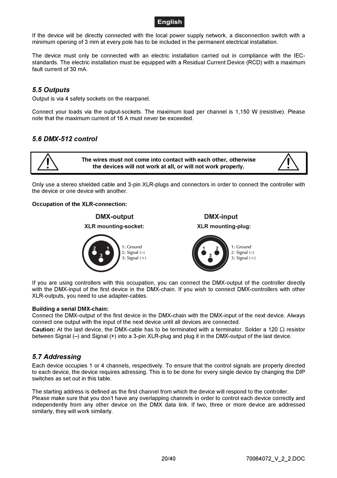
Occupation of the XLR-connection:
If you are using controllers with this occupation, you can connect the
Building a serial DMX-chain:
Connect the
Caution: At the last device, the
5.7 Addressing
Each device occupies 1 or 4 channels, respectively. To ensure that the control signals are properly directed to each device, the device requires adressing. This is to be done for every single device by changing the DIP switches as set out in this table.
The starting address is defined as the first channel from which the device will respond to the controller. Please make sure that you don’t have any overlapping channels in order to control each device correctly and independently from any other device on the DMX data link. If two, three or more device are addressed similarly, they will work similarly.
20/40 | 70064072_V_2_2.DOC |