Administrator’s Guide and Operating Instructions
2. Front & Rear Panels
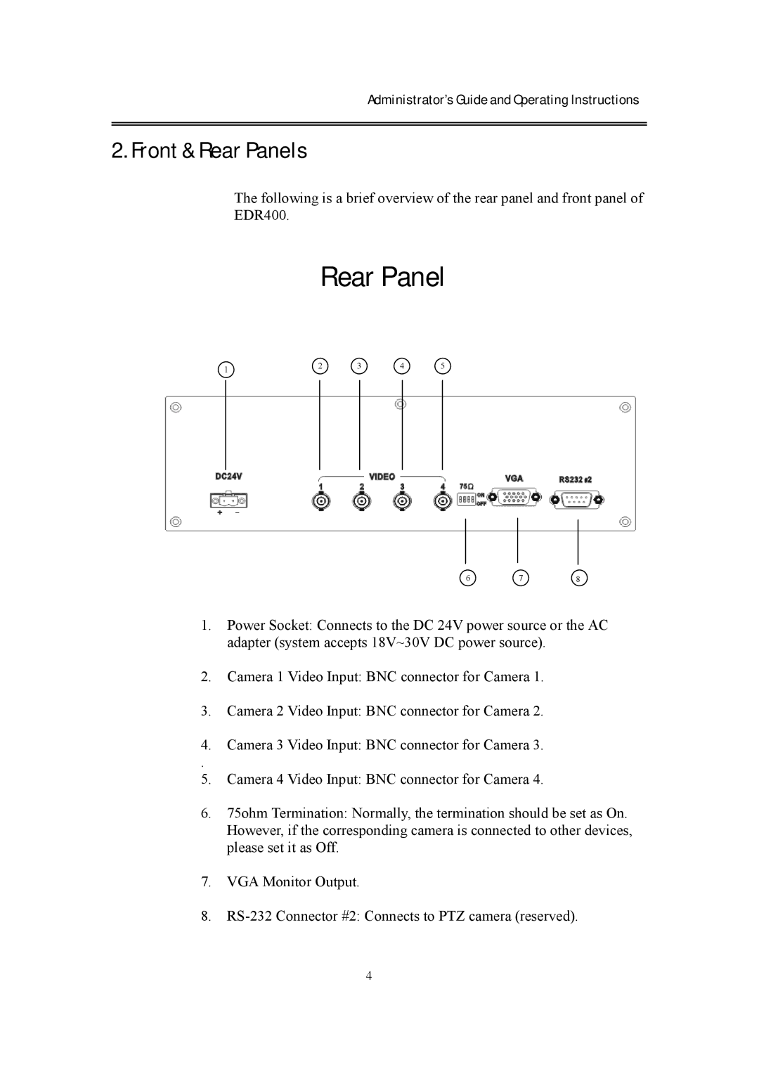
The following is a brief overview of the rear panel and front panel of EDR400.
Rear Panel
1 | 2 | 3 | 4 | 5 |
|
|
|
|
678
1.Power Socket: Connects to the DC 24V power source or the AC adapter (system accepts 18V~30V DC power source).
2.Camera 1 Video Input: BNC connector for Camera 1.
3.Camera 2 Video Input: BNC connector for Camera 2.
4.Camera 3 Video Input: BNC connector for Camera 3.
.
5.Camera 4 Video Input: BNC connector for Camera 4.
6.75ohm Termination: Normally, the termination should be set as On. However, if the corresponding camera is connected to other devices, please set it as Off.
7.VGA Monitor Output.
8.
4
