MENU
Note: Alarm Connectors
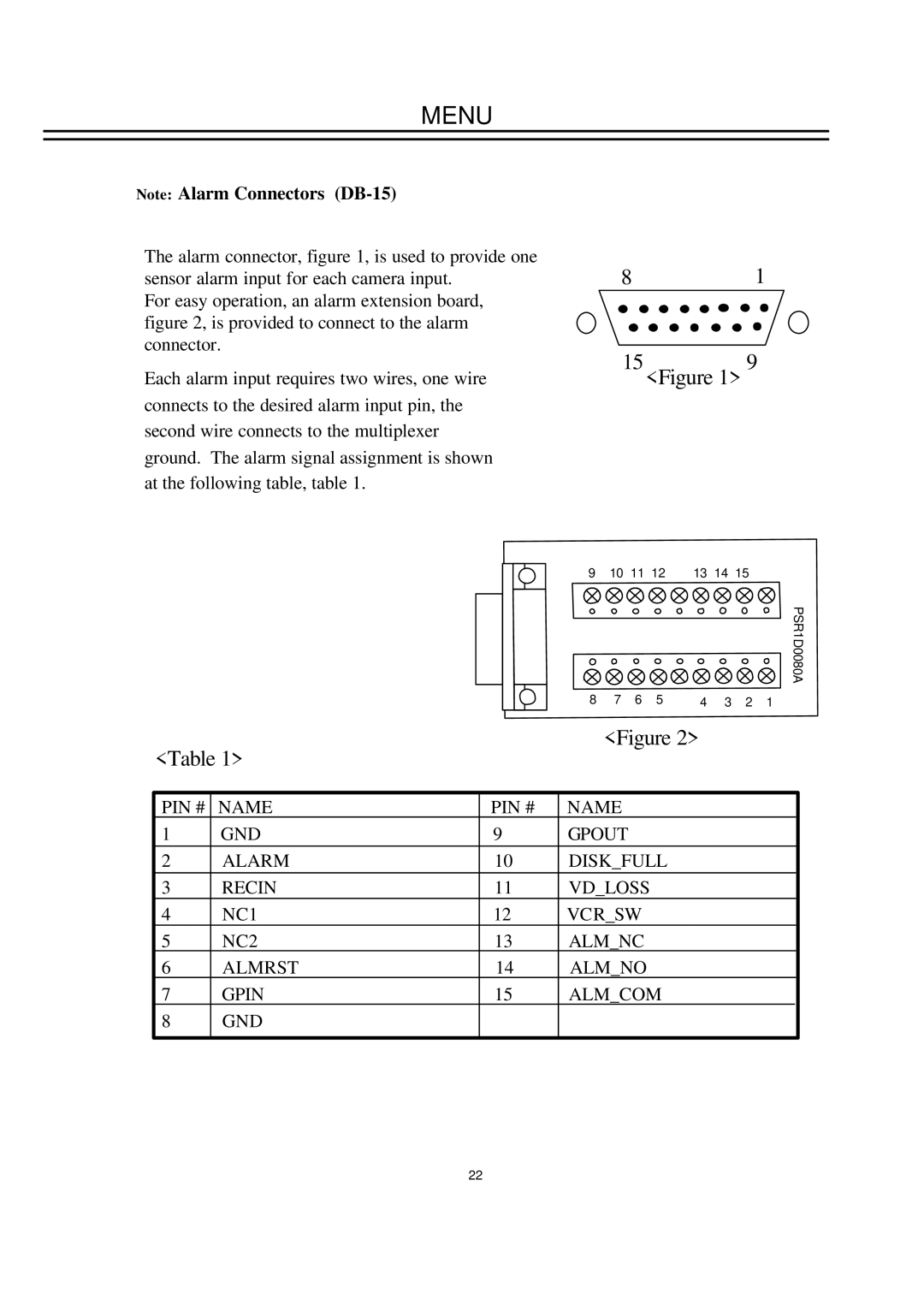
The alarm connector, figure 1, is used to provide one sensor alarm input for each camera input.
For easy operation, an alarm extension board, figure 2, is provided to connect to the alarm connector.
Each alarm input requires two wires, one wire connects to the desired alarm input pin, the second wire connects to the multiplexer ground. The alarm signal assignment is shown at the following table, table 1.
81
15<Figure 1> 9
|
|
| 9 | 10 11 12 | 13 14 15 |
| ||||
|
|
|
|
|
|
|
|
|
| PSR1D0080A |
|
|
| 8 | 7 | 6 | 5 | 4 | 3 | 2 | 1 |
<Table 1> |
|
| <Figure 2> |
|
|
| ||||
|
|
|
|
|
|
|
|
| ||
PIN # | NAME | PIN # | NAME |
|
|
|
|
|
| |
1 | GND | 9 | GPOUT |
|
|
|
|
|
| |
2 | ALARM | 10 | DISK_FULL |
|
|
|
| |||
3 | RECIN | 11 | VD_LOSS |
|
|
|
|
| ||
4 | NC1 | 12 | VCR_SW |
|
|
|
|
| ||
5 | NC2 | 13 | ALM_NC |
|
|
|
|
| ||
6 | ALMRST | 14 | ALM_NO |
|
|
|
|
| ||
7 | GPIN | 15 | ALM_COM |
|
|
|
| |||
8 | GND |
|
|
|
|
|
|
|
|
|
22