E V E R F O C U S E L E C T R O N I C S C O R P O R A T I O N
MONITOR
3
4
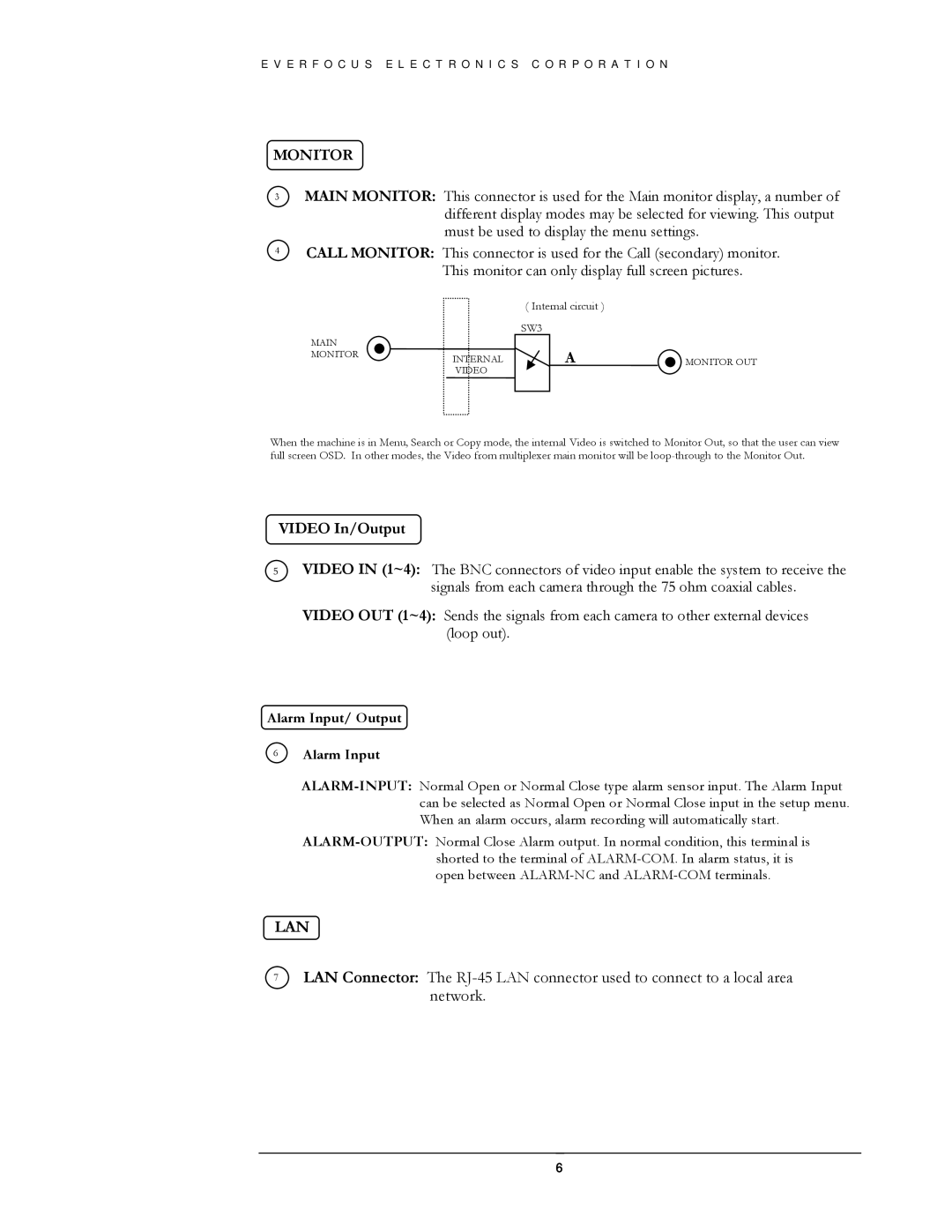
MAIN MONITOR: This connector is used for the Main monitor display, a number of different display modes may be selected for viewing. This output must be used to display the menu settings.
CALL MONITOR: This connector is used for the Call (secondary) monitor. This monitor can only display full screen pictures.
( Internal circuit )
SW3
MAIN |
|
|
|
MONITOR | INTERNAL | A | MONITOR OUT |
| VIDEO |
|
|
When the machine is in Menu, Search or Copy mode, the internal Video is switched to Monitor Out, so that the user can view full screen OSD. In other modes, the Video from multiplexer main monitor will be
VIDEO In/Output
5VIDEO IN (1~4): The BNC connectors of video input enable the system to receive the signals from each camera through the 75 ohm coaxial cables.
VIDEO OUT (1~4): Sends the signals from each camera to other external devices (loop out).
Alarm Input/ Output
6Alarm Input
LAN
7LAN Connector: The
6