3.ASSEMBLY INSTRUCTIONS
3.1UNCRATE MOWER
3.2INSTALL ROLLOVER PROTECTION SYSTEM (ROLL BAR)
3.2.1Disassemble roll bar from the crate.
a)Remove roll bar tubes from sides of crate and remove screws that attach the wheel hub retaining plate to the bottom of the crate.
b)Remove the two brackets used to mount the bottom of the upper roll bar tube to the crate. Remove the
3.2.2Raise the rear of the unit and support it with jack stands or equivalent support.
CAUTION
POTENTIAL HAZARD
♦Raising the rear of the unit for assembly relying solely on mechanical or hydraulic jacks could be dangerous.
WHAT CAN HAPPEN
♦The mechanical or hydraulic jacks may not be enough support or may malfunction allowing the unit to fall, which could cause injury.
HOW TO AVOID THE HAZARD
♦DO NOT rely solely on mechanical or hydraulic jacks for support. Use adequate jack stands or equivalent support.
3.2.3Remove the wheel nuts from both sides of the unit and retain for later use.
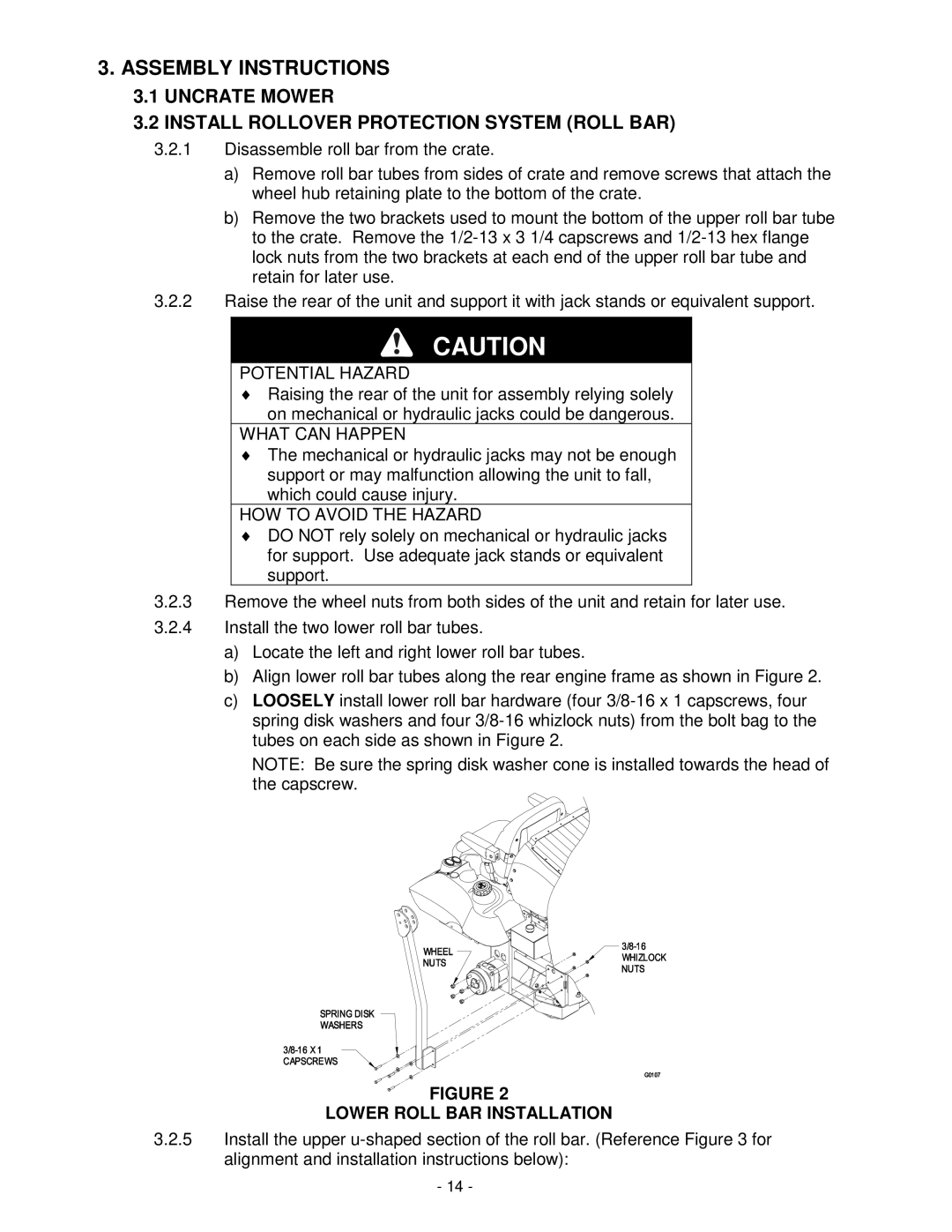
3.2.4Install the two lower roll bar tubes.
a)Locate the left and right lower roll bar tubes.
b)Align lower roll bar tubes along the rear engine frame as shown in Figure 2.
c)LOOSELY install lower roll bar hardware (four
NOTE: Be sure the spring disk washer cone is installed towards the head of the capscrew.
FIGURE 2
LOWER ROLL BAR INSTALLATION
3.2.5Install the upper
- 14 -