CrossPoint 84, 88, 124, 128, 168, and 1616 HV and HVA
CrossPoint Matrix Switchers
68-353-02 Rev. E Printed in the USA
Sicherheitsanleitungen Deutsch
Precautions
Safety Instructions English
Consignes de Sécurité Français
Definitions
Quick Start - CrossPoint Matrix Switchers
Installation
Configuration - One or more ties or sets of ties
Front Panel Controls
Quick Start - CrossPoint Matrix Switchers, cont’d
Save or recall a preset
View and adjust audio level
CrossPoint Matrix Switchers Table of Contents
Table of Contents
ii CrossPoint Matrix Switchers Table of Contents
Table of Contents, cont’d
Introduction
CrossPoint Matrix Switchers
About the CrossPoint Series Matrix Switchers Features
Chapter1One
About the CrossPoint Series Matrix Switchers
1-2 CrossPoint Matrix Switchers Introduction
Introductiontroduction, cont’d
Features
Figure 1-1 - A typical CrossPoint Matrix Switcher application
CrossPoint Matrix Switchers Introduction
Any input to any or all outputs
1-4 CrossPoint Matrix Switchers Introduction
Introduction, cont’d
Figure 1-2 - Audio gain and attenuation
CrossPoint Matrix Switchers Introduction
Introduction, cont’d
1-6 CrossPoint Matrix Switchers Introduction
CrossPoint Matrix Switchers
Installation
Rack Mounting the Switcher Cabling and Rear Panel Views
Chapter2Two
Figure 2-1 - Rear panel connectors, CrossPoint 128HVA
Installationstallation, cont’d
Rack Mounting the Switcher
Power connection
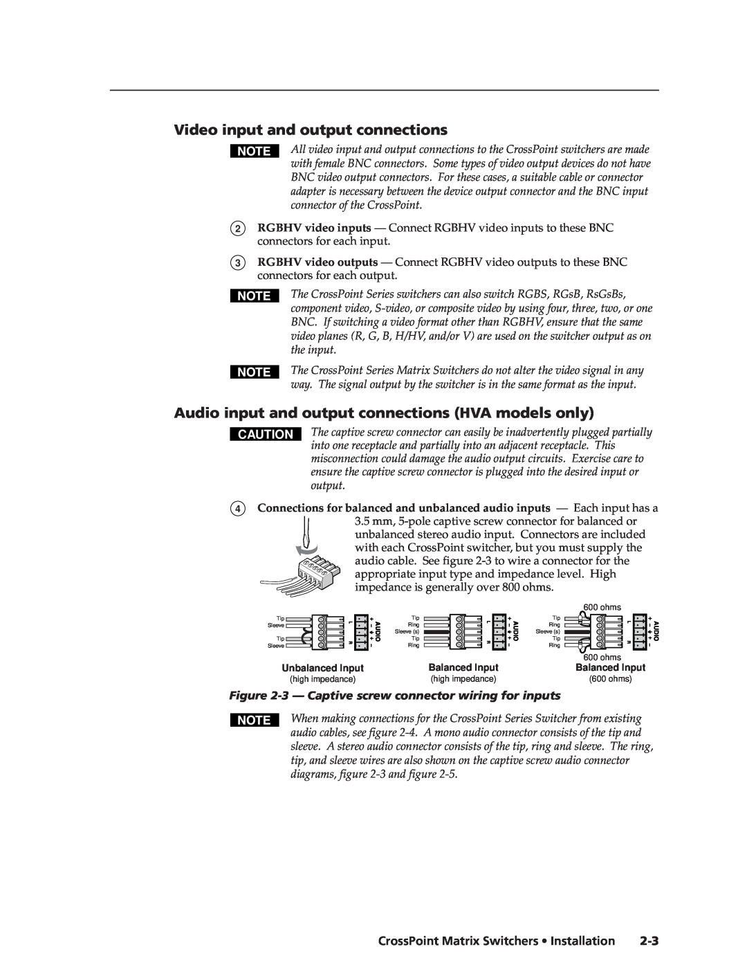
Audio input and output connections HVA models only
Figure 2-3 - Captive screw connector wiring for inputs
CrossPoint Matrix Switchers Installation
Video input and output connections
9-pin D connector for serial RS-232/422 control
Installation, cont’d
Figure 2-4 - Typical audio connectors
Figure 2-5 - Captive screw connector wiring for audio output
Figure 2-9 - Rear panel view, CrossPoint 88HVA
Figure 2-6 - Rear panel view, CrossPoint 84HV
Figure 2-7 - Rear panel view, CrossPoint 84HVA
Figure 2-8 - Rear panel view, CrossPoint 88HV
Figure 2-13 - Rear panel view, CrossPoint 168HV
2-6 CrossPoint Matrix Switchers Installation
Figure 2-11 - Rear panel view, CrossPoint 124HVA
Figure 2-12 - Rear panel view, CrossPoint 128HV
1 3 5
Figure 2-14 - Rear panel view, CrossPoint 168HVA
Figure 2-15 - Rear panel view, CrossPoint 1616HV
CrossPoint Matrix Switchers Installation
Installation, cont’d
2-8 CrossPoint Matrix Switchers Installation
Operation
Front Panel Controls and Indicators Front Panel Operations
Rear Panel Controls Troubleshooting Worksheets
Chapter3Three
Definitions
Front Panel Controls and Indicators
3-2 CrossPoint Matrix Switchers Operation
Operationeration, cont’d
CrossPoint Matrix Switchers Operation
Input buttons, output buttons, and LEDs
Control buttons and LEDs
Front panel I/O label windows
3-4 CrossPoint Matrix Switchers Operation
Operation, cont’d
I/O controls
CrossPoint Matrix Switchers Operation
Power
Creating a configuration
Front Panel Operations
Example 2 Add a tie to a set of video and audio ties
3-6 CrossPoint Matrix Switchers Operation
Example 1 Create a set of video and audio ties
Figure 3-4 - Example 1 Creating a tie
CrossPoint Matrix Switchers Operation
Figure 3-5 - Example 2 Adding a video tie
Example 3 Remove a tie from a set of video and audio ties
Figure 3-6 - Example 3 Selecting audio, selecting input
Example 4 View video and audio, audio-only, and video-only ties
Viewing a configuration
3-8 CrossPoint Matrix Switchers Operation
Figure 3-7 - Example 3, step D Removing an audio tie
CrossPoint Matrix Switchers Operation
3-10 CrossPoint Matrix Switchers Operation
Muting and unmuting video and/or audio
Operation, cont’d
Example 5 Muting and unmuting an output
CrossPoint Matrix Switchers Operation
1. You can mute video and audio, video-only, or audio-only outputs. Pressing and releasing the RGBHV and Audio buttons toggles each selection on and off
3-12 CrossPoint Matrix Switchers Operation
Using presets
Example 6 Save a preset
Figure 3-13 - Example 6 Saving the current configuration as preset
Example 8 View and adjust an audio level
Viewing and adjusting the audio level HVA models only
Example 7 Recall a preset
Figure 3-14 - Example 7 Recalling preset
3-14 CrossPoint Matrix Switchers Operation
Operation, cont’d
= off value 0 dB
Figure 3-16 - +8dB displayed, CrossPoint 168 and
Figure 3-18 - -1dB displayed, CrossPoint 168 and CrossPoint
CrossPoint Matrix Switchers Operation
3-16 CrossPoint Matrix Switchers Operation
Troubleshooting
Front panel security lockout executive mode
System reset to factory defaults
Worksheet example 1 Entering system equipment
Plasma display S-video problem
Worksheets
General checks
Operation, cont’d
Figure 3-20 - Worksheet example 2 Status meeting configuration
3-18 CrossPoint Matrix Switchers Operation
Worksheet example 2 Drawing ties
Worksheet example 3 Test configuration
Figure 3-21 - Worksheet example 3 Test configuration
CrossPoint Matrix Switchers Operation
Operation, cont’d
3-20 CrossPoint Matrix Switchers Operation
Indicate if the configuration is for Video, Audio, or both
Matrix Switchers Configuration Worksheet
CrossPoint Matrix Switchers Operation
Preset #
Operation, cont’d
3-22 CrossPoint Matrix Switchers Operation
Chapter4Four
Host-to-Switcher Instructions Switcher-Initiated Messages
Switcher Error Responses Using the Command/Response Table
Command/Response Table
4-2 CrossPoint Matrix Switchers Programmer’s Guide
Host-to-Switcher Instructions
Switcher-Initiated Messages
Figure 4-1 - RS-232/RS-422 connector pin arrangement
Switcher Error Responses
Using the Command/Response Table
CrossPoint Matrix Switchers Programmer’s Guide
Command
Command/Response Table
Command/response table for SIS commands
Symbol Definitions
CrossPoint Matrix Switchers Programmer’s Guide
Command/response table for SIS commands Cont’d
Command
ASCII Command
ASCII Command
4-6 CrossPoint Matrix Switchers Programmer’s Guide
Command/response table for SIS commands Cont’d
Command
CrossPoint Matrix Switchers
Matrix Switcher+ Control Program Button-Label Generator
Chapter5Five
Matrix Software
5-2 CrossPoint Matrix Switchers Matrix Software
Matrix Switcher+ Control Program
Installing the software
Using the software Overview
Windows buttons
Figure 5-1 - Extron Matrix Switcher+ Control Program window blank
CrossPoint Matrix Switchers Matrix Software
Figure 5-2 - Sample program window complete
File menu
5-4 CrossPoint Matrix Switchers Matrix Software
Matrix Software, cont’d
Windows menus
Button-Label Generator
Using emulation mode
Using the help system
Using the software
5-6 CrossPoint Matrix Switchers Matrix Software
Figure 5-3 - Extron’s Button-Label Generator window
Matrix Software, cont’d
CrossPoint Matrix Switchers
Specifications
Specifications Part Numbers
AAppendix A
Video input
Specificationsecifications, cont’d
A-2 CrossPoint Matrix Switchers Specifications
Video
Audio - audio models only
Control/remote - switcher
CrossPoint Matrix Switchers Specifications
General
Extron Part
Specifications, cont’d
A-4 CrossPoint Matrix Switchers Specifications
Part Numbers
Cables
RG6 super high resolution cable
Assorted connectors
BNC connectors
BNC-5 Mini HR Cable
A-6 CrossPoint Matrix Switchers Specifications
Specifications, cont’d
Extron Part
CrossPoint Matrix Switchers
Hardware Upgrades Button Labels
AppendixBB
Reference Information
Opening the CrossPoint 84, 88, 124, and
Hardware Upgrades
Opening the switcher
ReferenceInformation,co t’d
CrossPoint Matrix Switchers Reference Information
Opening the CrossPoint 168 and
Figure B-2 - Removing the front cover
Swapping the serial ports
Closing the switcher
B-4 CrossPoint Matrix Switchers Reference Information
Reference Information, cont’d
CrossPoint Matrix Switchers Reference Information
Installing a firmware update
Reconnect the input and output cables
Figure B-4 - Key and pin 1 mark
Reference Information, cont’d
B-6 CrossPoint Matrix Switchers Reference Information
Button Labels
Replacing the AC fuse CrossPoint 84, 88, 124, and 128 only
CrossPoint Matrix Switchers Reference Information
Figure B-5 - Button label blanks, 16-button strip
Reference Information, cont’d
B-8 CrossPoint Matrix Switchers Reference Information
Europe, Africa, and the Middle East
Extron’s Warranty
FCC Class A Notice
USA, Canada, South America
Extron Electronics, Japan
Extron Electronics, USA
Extron Electronics, Europe
Extron Electronics, Asia