Panels and
Cabling
This section covers the following:
•Front Panel Features
•Rear Panel Features and Cabling
•Application Diagrams
Front Panel Features
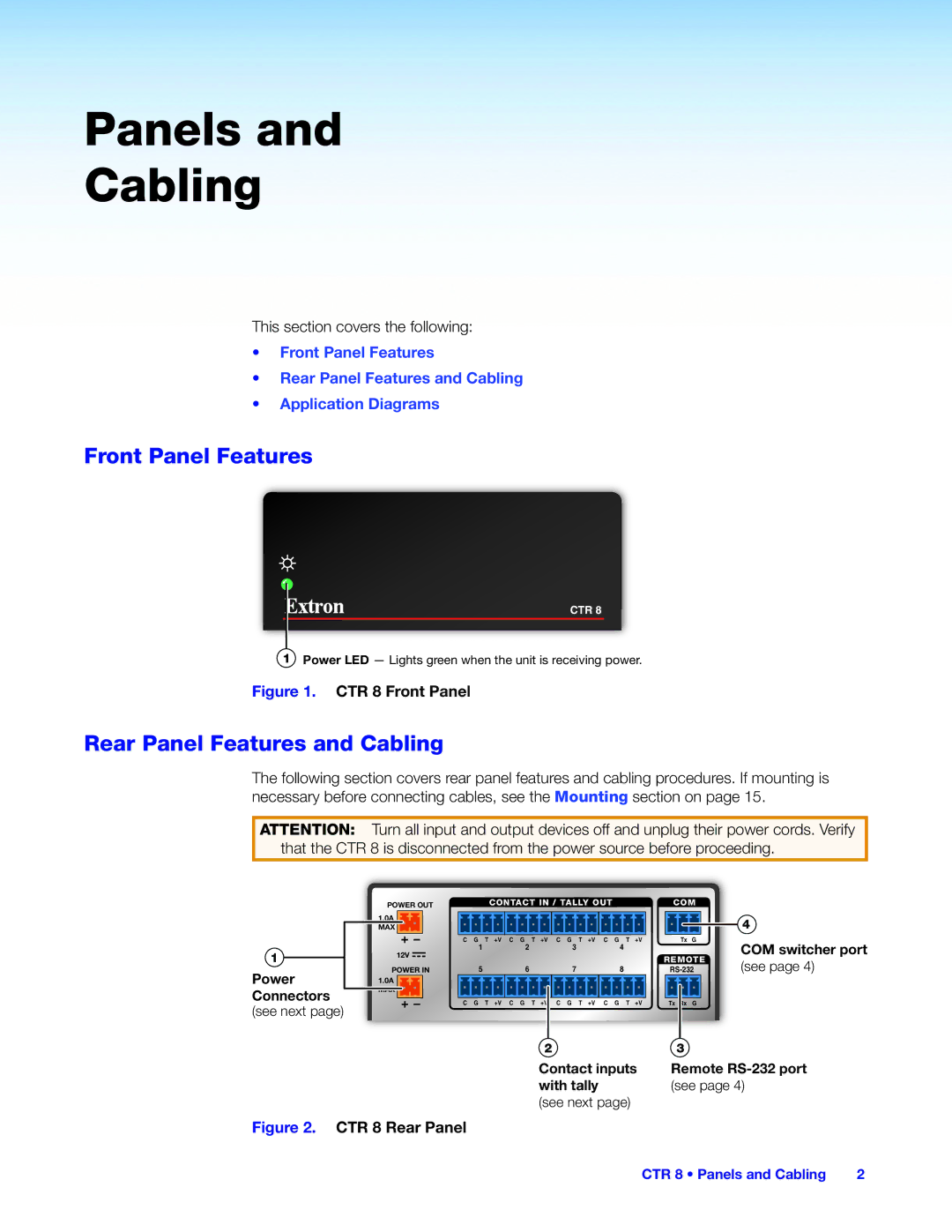
CTR 8
1Power LED — Lights green when the unit is receiving power.
Figure 1. CTR 8 Front Panel
Rear Panel Features and Cabling
The following section covers rear panel features and cabling procedures. If mounting is necessary before connecting cables, see the Mounting section on page 15.
ATTENTION: Turn all input and output devices off and unplug their power cords. Verify that the CTR 8 is disconnected from the power source before proceeding.
1 ![]()
Power
Connectors (see next page)
POWER OUT |
| CONTACT IN / TALLY OUT |
|
| COM | ||||
|
|
|
|
|
|
|
|
|
|
1.0A |
|
|
|
|
|
|
|
|
|
MAX |
|
|
|
|
|
|
|
|
|
|
|
| C G T +V C G T +V C G T +V C G T +V |
| Tx G | ||||
12V | 1 | 2 | 3 | 4 |
|
|
| ||
|
|
|
| REMOTE | |||||
|
|
|
|
|
|
| |||
POWER IN | 5 | 6 | 7 | 8 |
| ||||
1.0A |
|
|
|
|
|
|
|
|
|
MAX |
|
|
|
|
|
|
|
|
|
|
|
| C G T +V C G T +V C G T +V C G T +V |
| Tx Rx G | ||||
4
COM switcher port
(see page 4)
2 | 3 |
Contact inputs | Remote |
with tally | (see page 4) |
(see next page) |
|
Figure 2. CTR 8 Rear Panel
CTR 8 • Panels and Cabling | 2 |