A 1.0APOWER IN
MAX
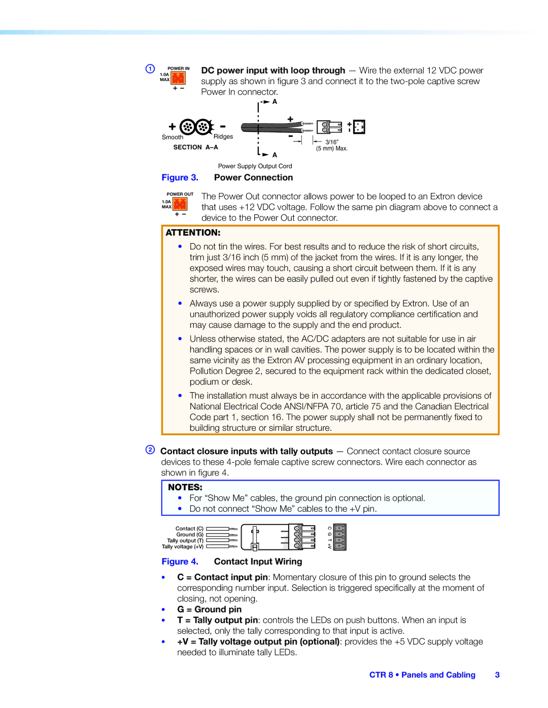
DC power input with loop through — Wire the external 12 VDC power supply as shown in figure 3 and connect it to the
![]() A
A
Smooth | Ridges | 3/16” | |
SECTION | |||
(5 mm) Max. | |||
|
| A | |
Figure 3.
POWER OUT
1.0A MAX
Power Supply Output Cord
Power Connection
The Power Out connector allows power to be looped to an Extron device that uses +12 VDC voltage. Follow the same pin diagram above to connect a device to the Power Out connector.
ATTENTION:
•Do not tin the wires. For best results and to reduce the risk of short circuits, trim just 3/16 inch (5 mm) of the jacket from the wires. If it is any longer, the exposed wires may touch, causing a short circuit between them. If it is any shorter, the wires can be easily pulled out even if tightly fastened by the captive screws.
•Always use a power supply supplied by or specified by Extron. Use of an unauthorized power supply voids all regulatory compliance certification and may cause damage to the supply and the end product.
•Unless otherwise stated, the AC/DC adapters are not suitable for use in air handling spaces or in wall cavities. The power supply is to be located within the same vicinity as the Extron AV processing equipment in an ordinary location, Pollution Degree 2, secured to the equipment rack within the dedicated closet, podium or desk.
•The installation must always be in accordance with the applicable provisions of National Electrical Code ANSI/NFPA 70, article 75 and the Canadian Electrical Code part 1, section 16. The power supply shall not be permanently fixed to building structure or similar structure.
BContact closure inputs with tally outputs — Connect contact closure source devices to these
NOTES:
•For “Show Me” cables, the ground pin connection is optional.
•Do not connect “Show Me” cables to the +V pin.
Contact (C) ![]()
![]() Ground (G)
Ground (G) ![]()
Tally output (T) ![]() Tally voltage (+V)
Tally voltage (+V) ![]()
C G T +V![]()
![]()
![]()
Figure 4. Contact Input Wiring
•C = Contact input pin: Momentary closure of this pin to ground selects the corresponding number input. Selection is triggered specifically at the moment of closing, not opening.
•G = Ground pin
•T = Tally output pin: controls the LEDs on push buttons. When an input is selected, only the tally corresponding to that input is active.
•+V = Tally voltage output pin (optional): provides the +5 VDC supply voltage needed to illuminate tally LEDs.
CTR 8 • Panels and Cabling | 3 |