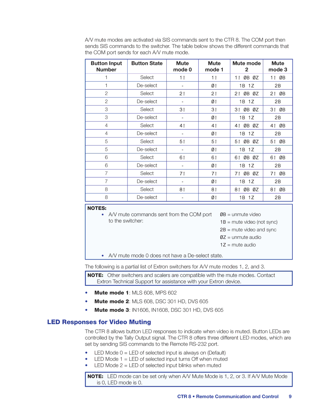
A/V mute modes are activated via SIS commands sent to the CTR 8. The COM port then sends SIS commands to the switcher. The table below shows the different commands that the COM port sends for each A/V mute mode.
Button Input | Button State | Mute | Mute | Mute mode | Mute | |
Number |
| mode 0 | mode 1 |
| 2 | mode 3 |
|
|
|
|
|
| |
1 | Select | 1! | 1! | 1! 0B 0Z | 1! 0B | |
|
|
|
|
|
|
|
1 | - | 0! | 1B | 1Z | 2B | |
|
|
|
|
|
| |
2 | Select | 2! | 2! | 2! 0B 0Z | 2! 0B | |
|
|
|
|
|
|
|
2 | - | 0! | 1B | 1Z | 2B | |
|
|
|
|
|
| |
3 | Select | 3! | 3! | 3! 0B 0Z | 3! 0B | |
|
|
|
|
|
|
|
3 | - | 0! | 1B | 1Z | 2B | |
|
|
|
|
|
| |
4 | Select | 4! | 4! | 4! 0B 0Z | 4! 0B | |
|
|
|
|
|
|
|
4 | - | 0! | 1B | 1Z | 2B | |
|
|
|
|
|
| |
5 | Select | 5! | 5! | 5! 0B 0Z | 5! 0B | |
|
|
|
|
|
|
|
5 | - | 0! | 1B | 1Z | 2B | |
|
|
|
|
|
| |
6 | Select | 6! | 6! | 6! 0B 0Z | 6! 0B | |
|
|
|
|
|
|
|
6 | - | 0! | 1B | 1Z | 2B | |
|
|
|
|
|
| |
7 | Select | 7! | 7! | 7! 0B 0Z | 7! 0B | |
|
|
|
|
|
|
|
7 | - | 0! | 1B | 1Z | 2B | |
|
|
|
|
|
| |
8 | Select | 8! | 8! | 8! 0B 0Z | 8! 0B | |
|
|
|
|
|
|
|
8 | - | 0! | 1B | 1Z | 2B | |
NOTES:
•A/V mute commands sent from the COM port to the switcher:
0B = unmute video
1B = mute video (not sync)
2B = mute video and sync
0Z = unmute audio
1Z = mute audio
•A/V mute mode 0 does not have a
The following is a partial list of Extron switchers for A/V mute modes 1, 2, and 3.
NOTE: Other switchers and scalers are compatible with the mute modes. Contact Extron Technical Support for assistance with your Extron device.
•Mute mode 1: MLS 608, MPS 602
•Mute mode 2: MLS 608, DSC 301 HD, DVS 605
•Mute mode 3: IN1606, IN1608, DSC 301 HD, DVS 605
LED Responses for Video Muting
The CTR 8 allows button LED responses to indicate when video is muted. Button LEDs are controlled by the Tally Output signal. The CTR 8 offers three different LED modes, which are set by sending SIS commands to the Remote
•LED Mode 0 = LED of selected input is always on (Default)
•LED Mode 1 = LED of selected input turns Off when muted
•LED Mode 2 = LED of selected input blinks when muted
NOTE: LED mode can be set only when A/V Mute Mode is 1, 2, or 3. If A/V Mute Mode is 0, LED mode is 0.
CTR 8 • Remote Communication and Control | 9 |
