Align the board edges with the plastic guides.

Removing and Installing a Power Supply Module (DMS 1600 and DMS 3600)

Each power supply module has a two-color LED, visible on the rear panel, that indicates the status of the power supply outputs. If the LED is lit green, the power supply is operating normally. If the LED is lit red, the supply has failed and should be replaced at the earliest opportunity. LEDs with identical meanings are also on the front panel.


1-8

A


CA

9-16


ANAHEIM,


A


17-24

A


25-32

REDUNDANT

422

RESET

BOTHPOWER BEFORESERVICING

PRIMARY


D


44 DVI


DMS


OUTPUTS

C

DVI-D

D


B


OUTPUTS

C

DVI-D


A


B


D

A


C


DVI-D

INPUTS

D


B


C


DVI-D

INPUTS


B


DVI


B


D

C

DVI-D

INPUTS


B

A

D 44 DVI

DMS


OUTPUTS

C

DVI-D


B

The two power supply modules (primary power supply and redundant power supply) are identical and hot-swappable; you do not need to power down the switcher to install or remove either power supply module.

ATTENTION: The DMS matrix switchers use double pole/ neutral fusing. Power must be disconnected before servicing internal components.

REMOTE RS-232/RS-

TRI-LEVELBI-LEVEL SWITCH

DISCONNECT CORDS

LAN ACTLINK

REFERENCE


A

IN

Knurled Knobs

NOTE: DMS 2000 and DMS 3200 — The power supplies are fixed in place and are not field replaceable.

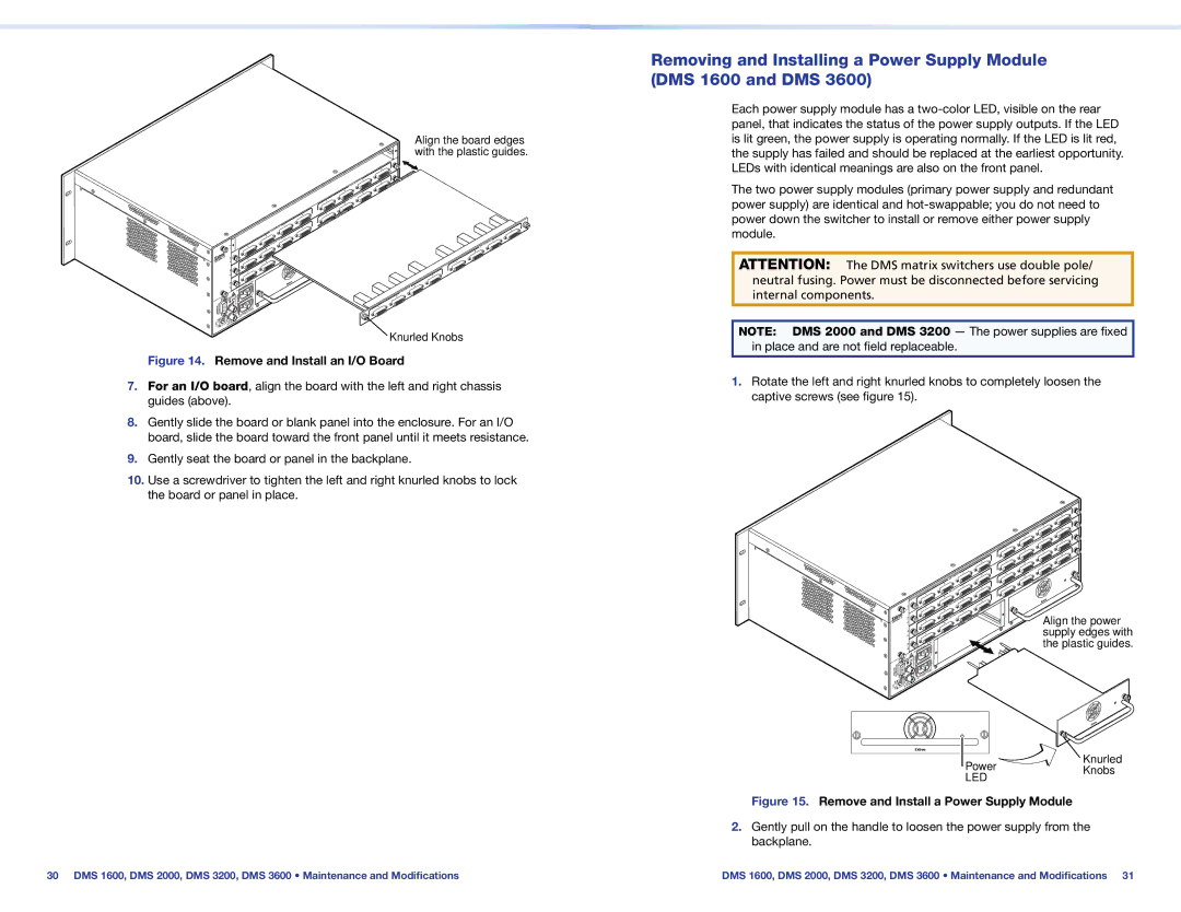
Figure 14. Remove and Install an I/O Board

7.For an I/O board, align the board with the left and right chassis guides (above).

8.Gently slide the board or blank panel into the enclosure. For an I/O board, slide the board toward the front panel until it meets resistance.

9.Gently seat the board or panel in the backplane.

10.Use a screwdriver to tighten the left and right knurled knobs to lock the board or panel in place.

1.Rotate the left and right knurled knobs to completely loosen the captive screws (see figure 15).


B


A


B


1-8


A


B

ANAHEIM,

CA

16-9


B


A


-1724


A


25-32


REDUNDANT

REMOTE RS-232/RS-422

TRI-LEVELBI-LEVEL RESET

SWITCH

DISCONNECTBOTHPOWER CORDSBEFORESERVICING

PRIMARY

LAN ACTLINK

REFERENCE


DVI-D

OUTPUTS


B


DVI-D

OUTPUTS


A


B


DVI-D

OUTPUTS


D

A


B


DVI-D

OUTPUTS


C


A


DVI-D

INPUTS

D

B


C

D

A


DVI-D

INPUTS


C


DVI-D

INPUTS

D


C


DVI-D

INPUTS


POWER


PRIMARY


D

44 DVI DMS C D

44 DVI DMS C D

44 DVI DMS C D

44 DVI DMS

C

SUPPLY

POWER

Align the power supply edges with the plastic guides.

Power

Knurled

Knobs

LED


Figure 15. Remove and Install a Power Supply Module

2.Gently pull on the handle to loosen the power supply from the backplane.

30 DMS 1600, DMS 2000, DMS 3200, DMS 3600 • Maintenance and Modifications

DMS 1600, DMS 2000, DMS 3200, DMS 3600 • Maintenance and Modifications 31

Page 21
Image 21
Extron electronic DMS 2000, DMS 3600, DMS 1600, DMS 3200 setup guide Remove and Install an I/O Board

DMS 3200, DMS 3600, DMS 1600, DMS 2000 specifications

Extron Electronics has long been a leader in the field of audio-visual integration, and their DMS family of switchers showcases their commitment to quality and innovation. The DMS 2000, DMS 1600, DMS 3600, and DMS 3200 are modular AV switching solutions designed to meet the needs of various AV applications, enhancing flexibility and functionality in managing signals.

The DMS 2000 is known for its exceptional ability to support a wide range of input and output configurations, making it suitable for various environments, from classrooms to corporate boardrooms. One of its main features is its modular construction, allowing users to customize the unit with different input and output cards based on the specific requirements of a project. This flexibility is coupled with Extron's exceptional scaling technology, which ensures high-quality video signal processing across diverse sources.

The DMS 1600, though smaller in capacity, still offers impressive features aimed at efficient signal management. This model can handle multiple HDMI inputs and outputs, positioning it well for smaller AV setups or as a stepping stone for upgrading existing systems. Its built-in EDID and HDCP management simplify integration with modern display devices, making it easier for users to connect multiple sources without worrying about compatibility issues.

Meanwhile, the DMS 3600 brings enhanced capabilities, boasting higher capacities suitable for larger installations. This model supports extensive audio routing options and extensive control capabilities, making it ideal for complex AV systems where seamless integration is critical. The advanced control options include support for various control systems, allowing users to integrate the DMS 3600 with existing technology seamlessly.

Lastly, the DMS 3200 offers features that are particularly appealing for installations that require both AV signal management and advanced control functionalities. Its robust processing capabilities ensure that it can handle high-resolution video signals with minimal latency. Additionally, the DMS 3200 excels in audio capabilities, supporting various audio formats and providing a comprehensive audio management system.

Overall, the DMS family of products from Extron Electronics stands out due to their modularity, advanced scaling technologies, and exceptional signal management capabilities. These characteristics make them ideal for a diverse range of applications, from educational environments to corporate settings, where flexibility and high performance are paramount. Their commitment to innovation and quality continues to position Extron Electronics at the forefront of AV technology.