Operation
This section details the connection of fiber optic cables to the equipment for testing and measuring the power loss of a fiber optic source.
•FPM 101 Power Meter — Controls and Connections
•FLS 101 Light Source — Controls and Connections
•Measuring Optical Power
•Testing Fiber Optic Links
•Testing Singlemode Links
•Using the Tone Generator
Transmit Reference | Mandrel |
Cable |
|
Coupler | Coupler |
|
| ||||||||
| or |
|
| or |
|
| |||||
Bulkhead | Bulkhead | Receive | |||||||||
|
|
|
|
|
|
|
|
|
| Reference Cable | |
|
|
|
|
| Multimode Fiber under Test |
|
| ||||
|
|
|
|
|
|
|
|
|
|
|
|
FLS 101
FIBER LIGHT SOURCE
MMSM
POWER
850nm
3.65dB
WAVE ID | 1300nm |
4.07dB
FPM 101
FIBER POWER METER ![]()
FLS 101 | FPM 101 | POWER |
Fiber Optic | Fiber Optic |
|
Light Source | Power Meter |
|
Transmit Reference |
| Receive | |
Cable |
| Reference Cable | |
Coupler | Singlemode Fiber under Test | Coupler | |
or | or | ||
| |||
Bulkhead |
| Bulkhead |
FLS 101
FIBER LIGHT SOURCE
MMSM
POWER
| 1310nmnm |
| 1.45dBdB |
WAVEID | 1550nmnm |
| 1.49dBdB |
FPM 101
FIBER POWER METER
FLS 101 | FPM 101 |
|
Fiber Optic | Fiber Optic | POWER |
Light Source | Power Meter |
|
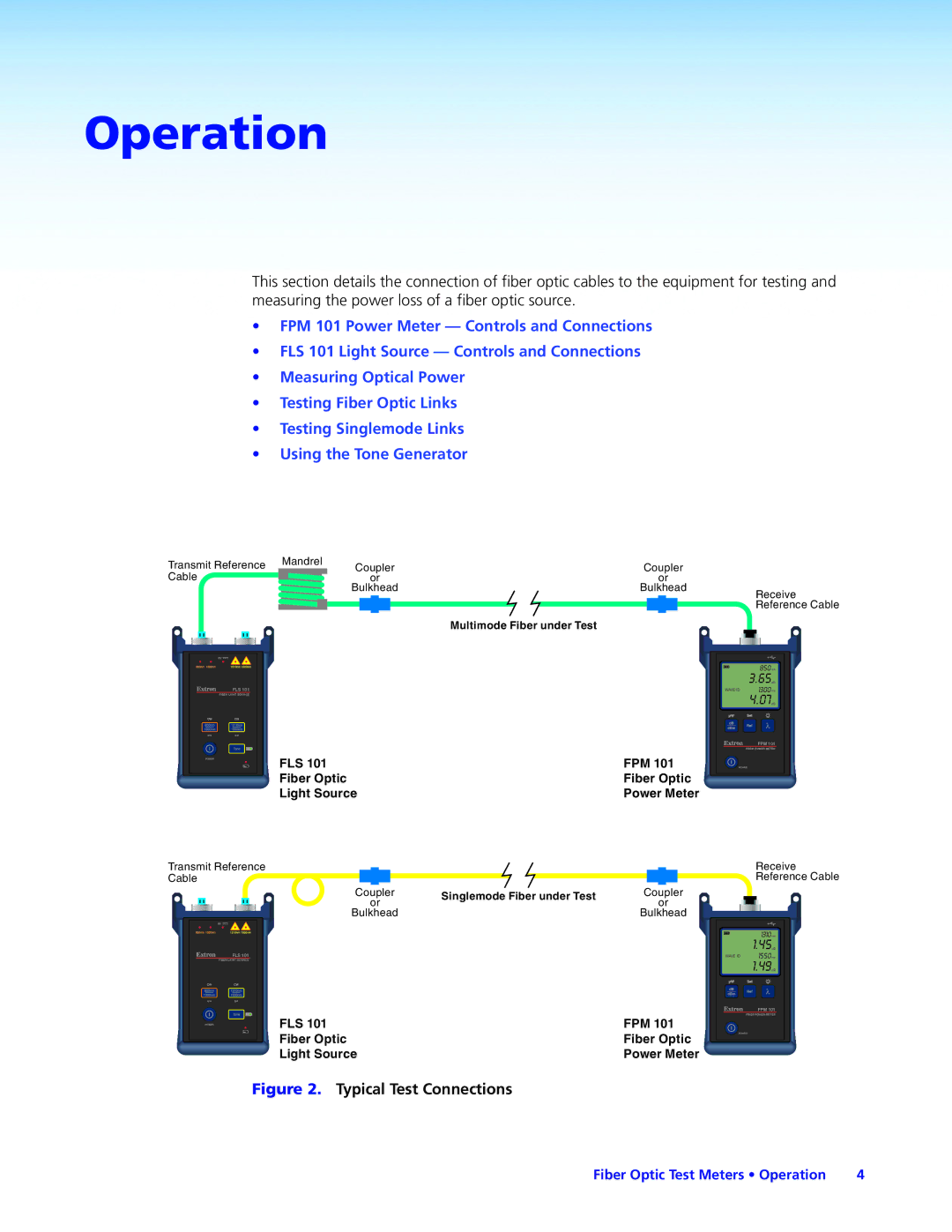
Figure 2. Typical Test Connections
Fiber Optic Test Meters • Operation | 4 |