FPM 101 Power Meter — Controls and Connections
a
b c
0000 | nm |
| Hz |
|
|
|
|
| 0.00 | ∝W | d |
|
|
|
|
|
|
| |
|
|
|
|
| 0000 | dB |
|
|
|
|
|
| nm |
| |
WAVE ID |
| Hz |
| ||||
0.00 |
|
| |||||
|
|
|
|
| ∝W |
| |
|
|
|
|
|
|
| |
|
|
|
|
|
| dB |
|
µW Set |
|
| ||
dB | Ref | λ | e | |
dBm | ||||
|
|
| ||
f
FPM 101
FIBER POWER METER
![]() POWER
POWER
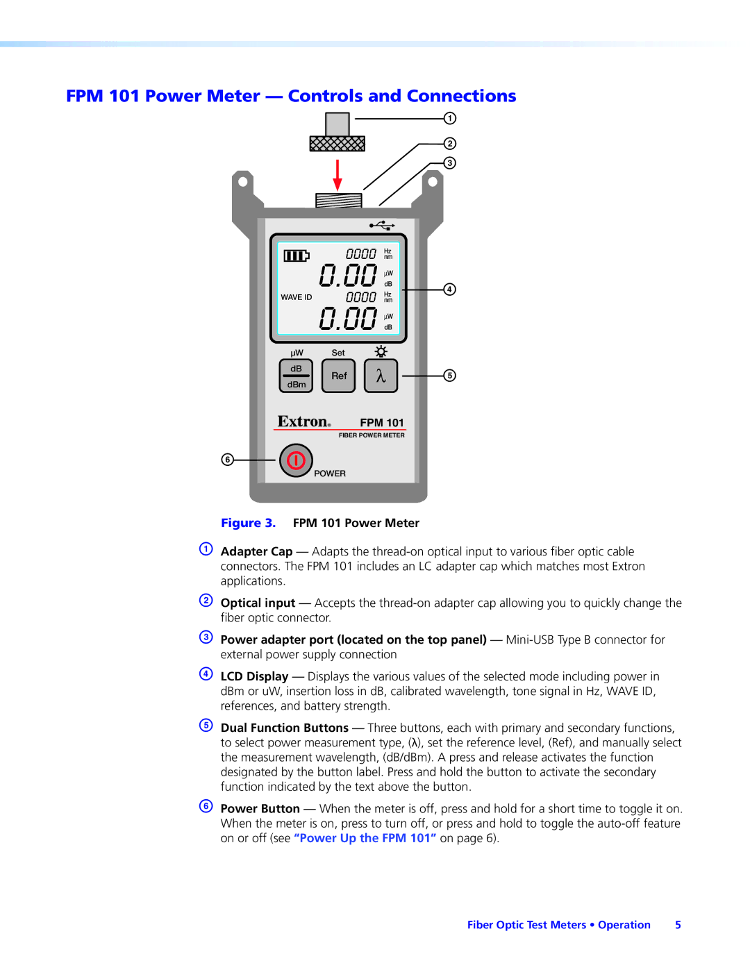
Figure 3. FPM 101 Power Meter
AAdapter Cap — Adapts the
BOptical input — Accepts the
CPower adapter port (located on the top panel) —
DLCD Display — Displays the various values of the selected mode including power in dBm or uW, insertion loss in dB, calibrated wavelength, tone signal in Hz, WAVE ID, references, and battery strength.
EDual Function Buttons — Three buttons, each with primary and secondary functions, to select power measurement type, (λ), set the reference level, (Ref), and manually select the measurement wavelength, (dB/dBm). A press and release activates the function designated by the button label. Press and hold the button to activate the secondary function indicated by the text above the button.
FPower Button — When the meter is off, press and hold for a short time to toggle it on. When the meter is on, press to turn off, or press and hold to toggle the
Fiber Optic Test Meters • Operation | 5 |
