2.Insert the link to be tested by connecting it to the free ends of the transmit and receive reference cables using appropriate couplings, or connect the reference cables to the bulkhead connections of the link as shown in figure 10 below.
![]() NOTE: Clean reference cable and link ends prior to each test.
NOTE: Clean reference cable and link ends prior to each test.
3.Observe the displayed values. The link cable insertion loss is displayed in dB.
![]() NOTE: If either the light source or power meter has shut off, turn it back on
NOTE: If either the light source or power meter has shut off, turn it back on ![]() and allow to stabilize for a minimum of two minutes.
and allow to stabilize for a minimum of two minutes.
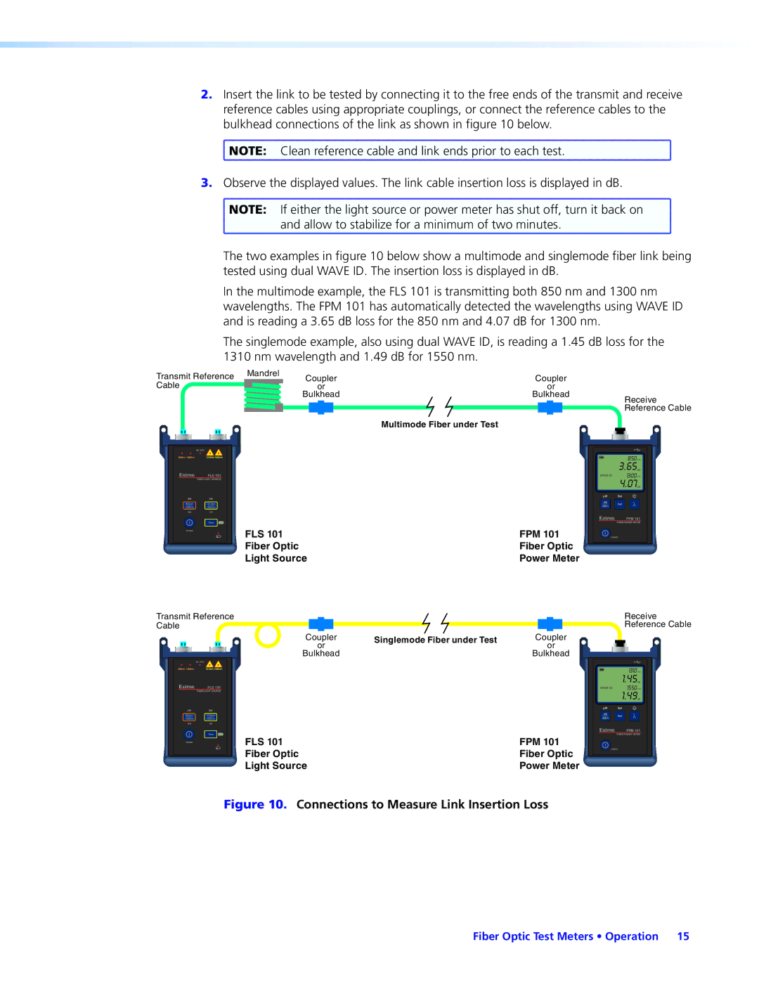
The two examples in figure 10 below show a multimode and singlemode fiber link being tested using dual WAVE ID. The insertion loss is displayed in dB.
In the multimode example, the FLS 101 is transmitting both 850 nm and 1300 nm wavelengths. The FPM 101 has automatically detected the wavelengths using WAVE ID and is reading a 3.65 dB loss for the 850 nm and 4.07 dB for 1300 nm.
The singlemode example, also using dual WAVE ID, is reading a 1.45 dB loss for the 1310 nm wavelength and 1.49 dB for 1550 nm.
Transmit Reference | Mandrel |
| |
Cable |
|
Coupler | Coupler |
| ||||||||
| or |
|
| or |
| |||||
Bulkhead | Bulkhead | Receive | ||||||||
|
|
|
|
|
|
|
|
|
| Reference Cable |
|
|
|
|
|
|
|
|
|
|
|
Multimode Fiber under Test
FLS 101
FIBER LIGHT SOURCE
MMSM
POWER
850nm
3.65dB
WAVE ID | 1300nm |
4.07dB
FPM 101
FIBER POWER METER ![]()
FLS 101 | FPM 101 | POWER |
Fiber Optic | Fiber Optic |
|
Light Source | Power Meter |
|
Transmit Reference |
| Receive | |
Cable |
| Reference Cable | |
Coupler | Singlemode Fiber under Test | Coupler | |
or | or | ||
| |||
Bulkhead |
| Bulkhead |
FLS 101
FIBER LIGHT SOURCE
MMSM
POWER
| 1310nmnm |
| 1.45dBdB |
WAVEID | 1550nmnm |
| 1.49dBdB |
FPM 101
FIBER POWER METER
FLS 101 | FPM 101 |
|
Fiber Optic | Fiber Optic | POWER |
Light Source | Power Meter |
|
Figure 10. Connections to Measure Link Insertion Loss
Fiber Optic Test Meters • Operation 15