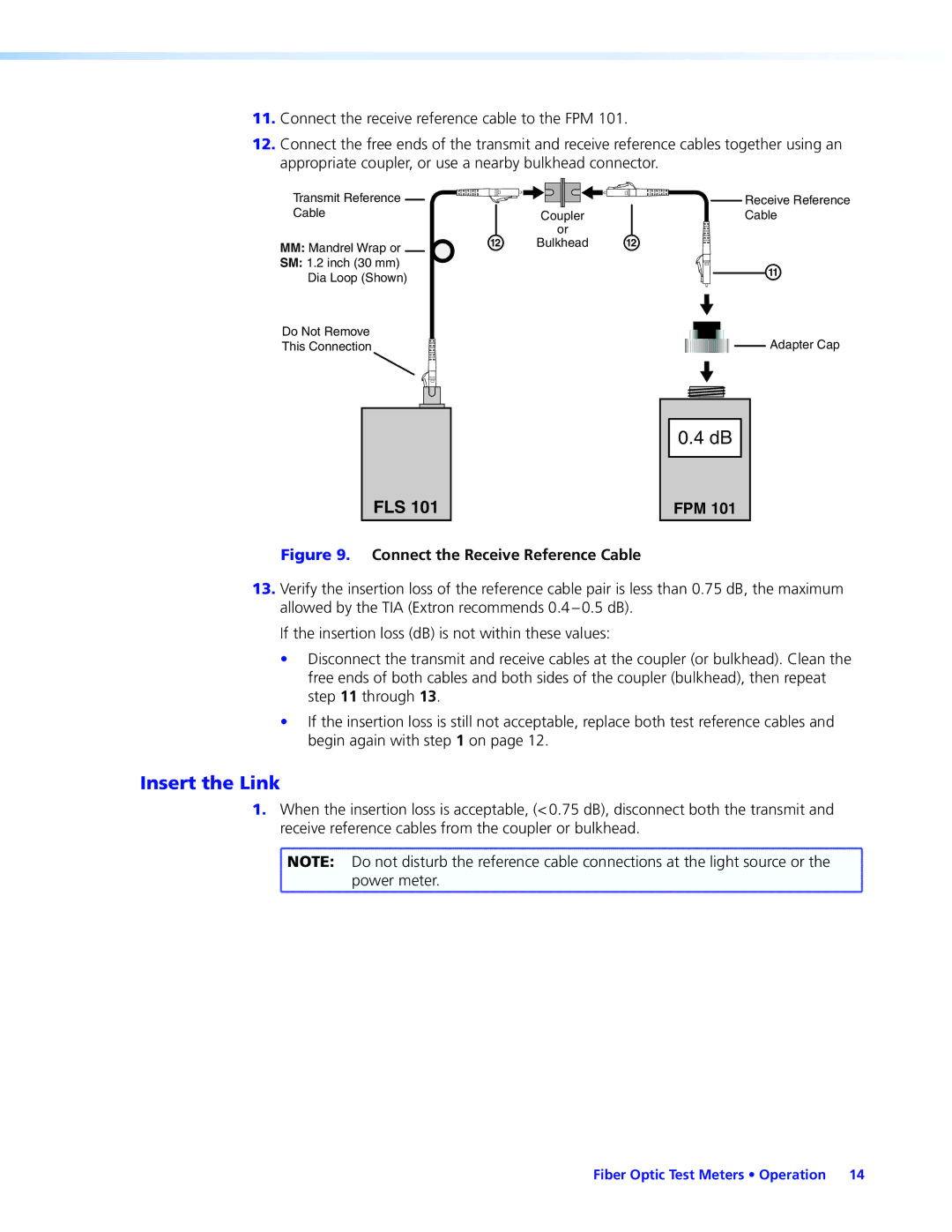
11.Connect the receive reference cable to the FPM 101.
12.Connect the free ends of the transmit and receive reference cables together using an appropriate coupler, or use a nearby bulkhead connector.
Transmit Reference |
|
| Receive Reference |
Cable |
| Coupler | Cable |
| N | or | N |
MM: Mandrel Wrap or | Bulkhead | ||
SM: 1.2 inch (30 mm) |
|
| M |
Dia Loop (Shown) |
|
| |
Do Not Remove |
|
| Adapter Cap |
This Connection |
|
|
FLS 101
0.4 dB |
FPM 101
Figure 9. Connect the Receive Reference Cable
13.Verify the insertion loss of the reference cable pair is less than 0.75 dB, the maximum allowed by the TIA (Extron recommends
If the insertion loss (dB) is not within these values:
•Disconnect the transmit and receive cables at the coupler (or bulkhead). Clean the free ends of both cables and both sides of the coupler (bulkhead), then repeat step 11 through 13.
•If the insertion loss is still not acceptable, replace both test reference cables and begin again with step 1 on page 12.
Insert the Link
1.When the insertion loss is acceptable, (< 0.75 dB), disconnect both the transmit and receive reference cables from the coupler or bulkhead.
![]() NOTE: Do not disturb the reference cable connections at the light source or the
NOTE: Do not disturb the reference cable connections at the light source or the ![]() power meter.
power meter.
Fiber Optic Test Meters • Operation 14