HDMI 201 Rx specifications
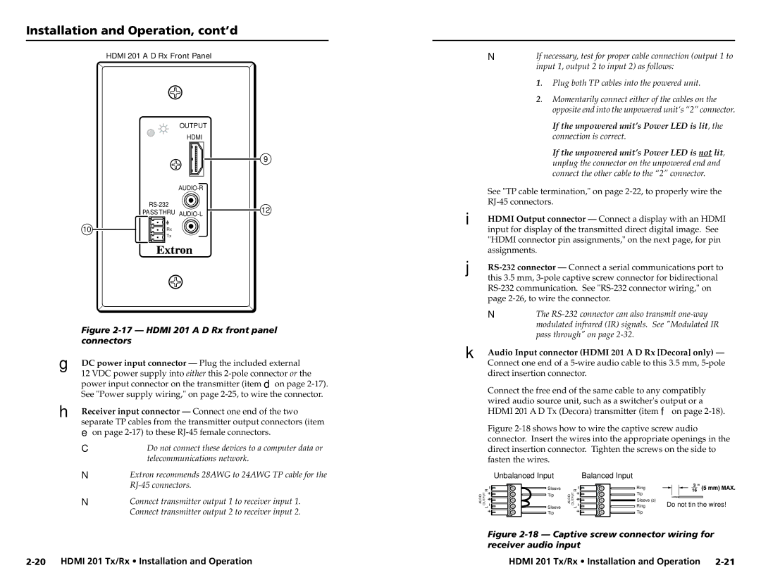
The Extron Electronics HDMI 201 Rx is a versatile and high-performing HDMI receiver designed for professional AV installations. This device is engineered to extend HDMI signals up to 230 feet (70 meters) using a single Cat 6a or better cable, ensuring that high-definition video and audio can be transmitted over long distances without compromising quality.One of the standout features of the HDMI 201 Rx is its ability to support resolutions up to 4K at 30Hz, along with 1080p video at 60Hz. This makes it an excellent choice for environments where crisp, high-resolution visuals are critical, such as classrooms, conference rooms, and auditoriums. The receiver also supports various audio formats, including LPCM, Dolby Digital, and DTS, ensuring that users receive a comprehensive audio experience.
Another key technology employed in the HDMI 201 Rx is EDID (Extended Display Identification Data) management, which allows the receiver to communicate with connected displays to ensure optimal performance. This feature helps prevent compatibility issues and guarantees that the video output is tailored to the capabilities of the display device.
The HDMI 201 Rx also incorporates a unique feature known as HDBaseT technology, which enables the transfer of HDMI signals, Ethernet, and power over the same cable. This simplifies overall installation, reducing cable clutter and minimizing the number of required components. Additionally, the receiver includes built-in support for Power over Ethernet (PoE), allowing it to be powered through the same cable that carries the data signal, which can be a game-changer for ease of installation.
Integrators will appreciate the compact design and low-profile form factor of the HDMI 201 Rx, which allows for discreet integration into various environments. The unit is equipped with a set of LED indicators that provide real-time feedback on power, link status, and signal presence, helping installers monitor performance and troubleshoot effectively.
In conclusion, the Extron HDMI 201 Rx is a robust solution for extending HDMI signals over long distances while maintaining high-quality video and audio performance. With its support for 4K resolution, EDID management, HDBaseT technology, and PoE capabilities, it meets the demands of modern AV installations, making it a reliable choice for professionals in the industry.

