Hardware Setup, cont’d
Volume control
C | Volume knob and LEDs — Rotate this knob to adjust the audio |
| volume. Global Configurator lets you select whether this |
| knob will control the projector’s audio levels or the optional |
| MediaLink switcher’s audio levels. |
| If the MLC is configured for use with a MediaLink Switcher |
| or projectors, the MLC’s LEDs light to indicate volume ranges |
| (with steadily lit LEDs) and minimum/maximum volume limits |
| (with flashing LEDs). |
| If the MLC is configured for increment/decrement volume |
| adjustment, the LEDs scroll up/down briefly. |
Configuration (host control) port
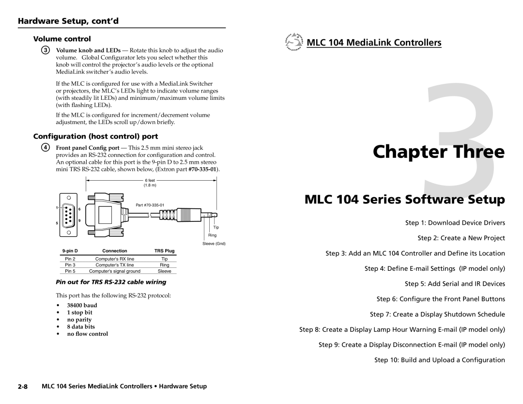
D | Front panel Config port — This 2.5 mm mini stereo jack | |||||
| provides an | |||||
| An optional cable for this port is the | |||||
| mini TRS RS‑232 cable, shown below, (Extron part | |||||
|
|
|
| 6 feet |
|
|
|
|
|
|
|
| |
|
|
|
|
| ||
|
|
|
| (1.8 m) | ||
|
|
|
|
|
|
|


 MLC 104 MediaLink Controllers
Chapter3Three
1![]()
![]() 6
6
Part
MLC 104 Series Software Setup
5
9
Step 1: Download Device Drivers
Tip
Ring
Sleeve (Gnd)
Connection | TRS Plug | |
|
|
|
Pin 2 | Computer's RX line | Tip |
Pin 3 | Computer's TX line | Ring |
Pin 5 | Computer's signal ground | Sleeve |
Pin out for TRS RS-232 cable wiring
This port has the following
•38400 baud
•1 stop bit
•no parity
•8 data bits
•no flow control
Step 2: Create a New Project
Step 3: Add an MLC 104 Controller and Define its Location Step 4: Define
Step 5: Add Serial and IR Devices
Step 6: Configure the Front Panel Buttons
Step 7: Create a Display Shutdown Schedule
Step 8: Create a Display Lamp Hour Warning
Step 10: Build and Upload a Configuration