![]() NOTE: The receiver
NOTE: The receiver ![]()
![]() TP input is audio or
TP input is audio or ![]()
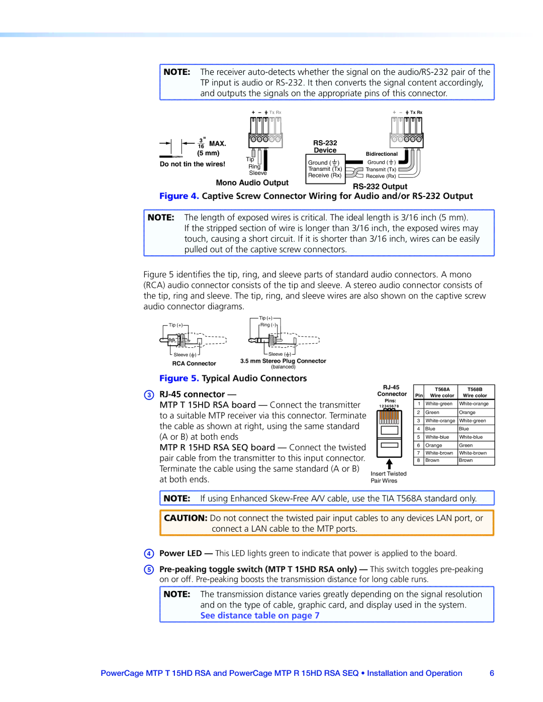
![]() and outputs the signals on the appropriate pins of this connector.
and outputs the signals on the appropriate pins of this connector. ![]()
|
|
|
|
|
| Tx Rx | Tx Rx | ||||||||||||
|
|
|
|
|
|
|
|
|
|
|
|
|
|
|
|
|
|
|
|
|
|
|
|
|
|
|
|
|
|
|
|
|
|
|
|
|
|
|
|
|
|
|
|
|
|
|
|
|
|
|
|
|
|
|
|
|
|
|
|
Do not tin the wires! | Tip |
Ring | |
| Sleeve |
Mono Audio Output
| |
Device | Bidirectional |
| |
Ground ( ) | Ground ( ) |
Transmit (Tx) | Transmit (Tx) |
Receive (Rx) | Receive (Rx) |
|
Figure 4. Captive Screw Connector Wiring for Audio and/or RS-232 Output
![]() NOTE: The length of exposed wires is critical. The ideal length is 3/16 inch (5 mm).
NOTE: The length of exposed wires is critical. The ideal length is 3/16 inch (5 mm).
If the stripped section of wire is longer than 3/16 inch, the exposed wires may
touch, causing a short circuit. If it is shorter than 3/16 inch, wires can be easily pulled out of the captive screw connectors.
Figure 5 identifies the tip, ring, and sleeve parts of standard audio connectors. A mono (RCA) audio connector consists of the tip and sleeve. A stereo audio connector consists of the tip, ring and sleeve. The tip, ring, and sleeve wires are also shown on the captive screw audio connector diagrams.
| Tip (+) | |
Tip (+) | Ring | |
Sleeve ( ) | Sleeve ( ) | |
RCA Connector | 3.5 mm Stereo Plug Connector | |
(balanced) | ||
|
Figure 5. Typical Audio Connectors
cRJ-45 connector —
MTP T 15HD RSA board — Connect the transmitter to a suitable MTP receiver via this connector. Terminate the cable as shown at right, using the same standard (A or B) at both ends
MTP R 15HD RSA SEQ board — Connect the twisted pair cable from the transmitter to this input connector. Terminate the cable using the same standard (A or B) at both ends.
|
| T568A | T568B | |||
Connector |
| |||||
Pin | Wire color | Wire color | ||||
| Pins: | 1 | ||||
1 2 3 4 5 6 7 8 |
|
| ||||
|
|
|
|
| ||
|
|
|
| 2 | Green | Orange |
|
|
|
| |||
|
|
|
|
|
|
|
|
|
|
| 3 | ||
|
|
|
| 4 | Blue | Blue |
|
|
|
| |||
|
|
|
|
|
|
|
|
|
|
| 5 | ||
|
|
|
| |||
|
|
|
|
|
|
|
|
|
|
| 6 | Orange | Green |
|
|
|
| |||
|
|
|
| 7 | ||
|
|
|
|
|
|
|
|
|
|
| 8 | Brown | Brown |
|
|
|
|
|
|
|
Insert Twisted
Pair Wires
![]() NOTE: If using Enhanced
NOTE: If using Enhanced
![]() CAUTION: Do not connect the twisted pair input cables to any devices LAN port, or connect a LAN cable to the MTP ports.
CAUTION: Do not connect the twisted pair input cables to any devices LAN port, or connect a LAN cable to the MTP ports.
dPower LED — This LED lights green to indicate that power is applied to the board.
e
![]() NOTE: The transmission distance varies greatly depending on the signal resolution
NOTE: The transmission distance varies greatly depending on the signal resolution ![]() and on the type of cable, graphic card, and display used in the system.
and on the type of cable, graphic card, and display used in the system.
See distance table on page 7
PowerCage MTP T 15HD RSA and PowerCage MTP R 15HD RSA SEQ • Installation and Operation | 6 |