Controls and Installation, cont’d
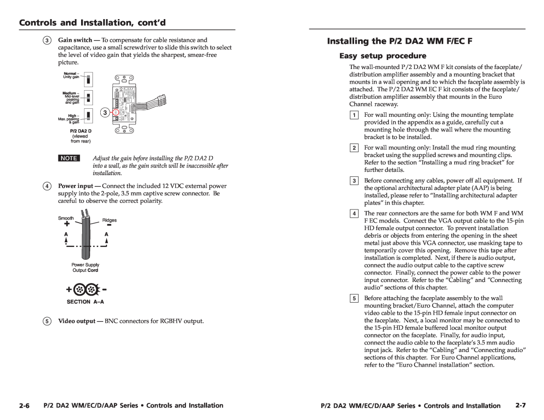
3Gain switch — To compensate for cable resistance and capacitance, use a small screwdriver to slide this switch to select the level of video gain that yields the sharpest,
Normal –
Unity gain ![]()
![]()
Medium – | 1 2 3 4 | ON | AUDIO OUTPUT LR 1 2 34 | SW 4= Sp are | OFF= 10 kOhm | ON= 510 Ohm, | SW 3= SYNC Inpu t aImpednce | P/2 DA2 D CONFIG Switches SW 1= Loc al Monitor ON= Present, OFF= NotPresent SW 2= A udio Ou pu tConfig ON=Stereo, OFF= D ua lMONO | |
|
|
| CONFIG |
|
|
|
|
| |
peaking |
|
|
|
|
|
|
|
|
|
and gain |
|
|
|
|
|
|
|
|
|
| 3 |
| NORM |
|
| OUTPUT | VIDEO |
|
|
|
|
| HIGH | GAIN | VIDEO |
|
|
|
|
Max. peaking |
|
| MED | POWER 12V | N15779 | Anaheim,CA | ExtronElectronics | 33 | |
|
| 0.2AMAX | |||||||
High – |
|
|
|
|
|
|
|
|
|
& gain |
|
|
|
|
|
|
|
| 08 |
P/2 DA2 D (viewed from rear)
NAdjust the gain before installing the P/2 DA2 D
into a wall, as the gain switch will be inaccessible after installation.
4Power input — Connect the included 12 VDC external power supply into the
Smooth | Ridges |
A | A |
Power Supply
Output Cord
SECTION
5Video output — BNC connectors for RGBHV output.
Installing the P/2 DA2 WM F/EC F
Easy setup procedure
The
1For wall mounting only: Using the mounting template provided in the appendix as a guide, carefully cut a mounting hole through the wall where the mounting bracket is to be installed.
2For wall mounting only: Install the mud ring mounting bracket using the supplied screws and mounting clips. Refer to the section “Installing a mud ring bracket” for further details.
3Before connecting any cables, power off all equipment. If the optional architectural adapter plate (AAP) is being installed, please refer to “Installing architectural adapter plates” in this chapter.
4The rear connectors are the same for both WM F and WM F EC models. Connect the VGA output cable to the
5Before attaching the faceplate assembly to the wall mounting bracket/Euro Channel, attach the computer video cable to the
P/2 DA2 WM/EC/D/AAP Series • Controls and Installation | P/2 DA2 WM/EC/D/AAP Series • Controls and Installation |