Controls and Installation, cont’d
Setting the internal jumpers
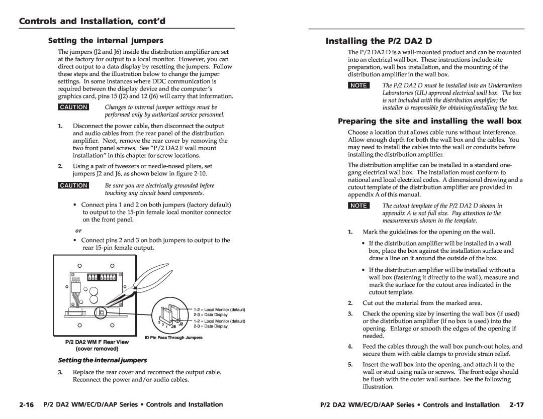
The jumpers (J2 and J6) inside the distribution amplifier are set at the factory for output to a local monitor. However, you can direct output to a data display by resetting the jumpers. Follow these steps and the illustration below to change the jumper settings. In some instances where DDC communication is required between the display device and the computer’s graphics card, pins 15 (J2) and 12 (J6) will carry that information.
CChanges to internal jumper settings must be performed only by authorized service personnel.
1.Disconnect the power cable, then disconnect the output and audio cables from the rear panel of the distribution amplifier. Next, remove the rear cover by removing the two front panel screws. See “P/2 DA2 F wall mount installation” in this chapter for screw locations.
2.Using a pair of tweezers or
CBe sure you are electrically grounded before touching any circuit board components.
•Connect pins 1 and 2 on both jumpers (factory default) to output to the
or
•Connect pins 2 and 3 on both jumpers to output to the rear
|
| = Local Monitor (default) | |
|
| ||
3 | J2 | = Local Monitor (default) | |
2 1 J6 | |||
ID Pin Pass Through Jumpers
P/2 DA2 WM F Rear View
(cover removed)
Setting the internal jumpers
3.Replace the rear cover and reconnect the output cable. Reconnect the power and/or audio cables.
Installing the P/2 DA2 D
The P/2 DA2 D is a
NThe P/2 DA2 D must be installed into an Underwriters Laboratories (UL) approved electrical wall box. The box is not included with the distribution amplifier; the installer is responsible for obtaining/installing the box.
Preparing the site and installing the wall box
Choose a location that allows cable runs without interference. Allow enough depth for both the wall box and the cables. You may need to install the cables into the wall or conduits before installing the distribution amplifier.
The distribution amplifier can be installed in a standard one- gang electrical wall box. The installation must conform to national and local electrical codes. A dimensional drawing and a cutout template of the distribution amplifier are provided in appendix A of this manual.
NThe cutout template of the P/2 DA2 D shown in appendix A is not full size. Pay attention to the measurements shown in the template.
1.Mark the guidelines for the opening on the wall.
•If the distribution amplifier will be installed in a wall box, place the box against the installation surface and draw a line on it around the outside of the box.
•If the distribution amplifier will be installed without a wall box (fastening it directly to the wall), measure and mark the surface for the cutout area indicated in the cutout template.
2.Cut out the material from the marked area.
3.Check the opening size by inserting the wall box (if used) or the distribution amplifier (if no box is used) into the opening. Enlarge or smooth the edges of the opening if needed.
4.Feed the cables through the wall box
5.Insert the wall box into the opening, and attach it to the wall or stud using nails or screws. The front edge should be flush with the outer wall surface. See the following illustration.
P/2 DA2 WM/EC/D/AAP Series • Controls and Installation |