Americas Headquarters
Cisco Nexus 5000 Series Hardware Installation Guide
Page
Iii
Cisco Nexus 5548UP and 5548P Switches
Replacing Components
Replacing or Installing Power Supplies
LEDs D-1
Viii
Audience
Organization
Chapter and Title Description
Bewaar Deze Instructies
Conventions
Warnung Wichtige Sicherheitshinweise
Avvertenza Importanti Istruzioni Sulla Sicurezza
Aviso Instruções Importantes DE Segurança
Spara Dessa Anvisningar
GEM Disse Anvisninger
Xiv
Preface
Release Notes
Configuration Guides
Installation and Upgrade Guides
Related Documentation
Licensing Guide
Command References
Error and System Messages
Troubleshooting Guide
Xviii
A P T E R
Cisco Nexus 5500 Platform Switches
Cisco Nexus 5596UP Switch
Features
Chassis
Front View of the Cisco Nexus 5596UP Switch
Expansion Modules
Rear View of the Cisco Nexus 5596UP Switch
Port Universal GEM2
Port Qsfp GEM
Layer 3 GEM
Ports
Part Number Power Supply
Power Supply
9shows the NXA-PAC-1100W
10NXA-PAC-1100W-B
Fan Module
SFP+ Transceivers
Transceivers
Cwdm Optics
Cisco Nexus 5596T Switch
SFP+ Copper Cables
SFP Fibre Channel Transceivers
Features
13 Front View of the Cisco Nexus 5596T Switch
15shows how ports are numbered and grouped by function
SFP-10G-LR= SFP-10G-ER=
Cisco Nexus 5548UP and 5548P Switches
Transceivers and Cables,
ID LED
ID LED
N55 M16P Generic Expansion Module
N55 M8P8FP Generic Expansion Module
18 Components Used to Install the N55 M16P GEM
N55 M16UP Generic Expansion Module
20 Components Used to Install the N55 M8P8FP GEM
Data Ports
Power Supplies
Part Number Power Supply
Fail top and OK bottom LEDs Release latch Handle
Fan Modules
Transceivers and Cables
Transceivers
Cisco SFP Description
SFP-10G-SR SFP-10G-LR
DS-SFP-FC4G-LW
Cables
Standard
Cisco Nexus 5000 Platform Switches
Cisco Nexus 5020 Switch
Power Each Transceiver Connector Media Cable Distance Side
Two power supplies System status LED Five fan modules
28 Cisco Nexus 5020 Switch Rear View
Fibre Channel Plus Ethernet Expansion Module
30 Fibre Channel Plus Ethernet Expansion Module Features
31shows the Ethernet and Fibre Channel ports are numbered
Ethernet Expansion Module
N5K-M1060 Generic Expansion Module
N5K-M1008 Generic Expansion Module
Six 8-, 4-, 2-, or 1-Gbps Fibre Channel ports
186386
Fault top and OK bottom LEDs Handle Release lever
Fan module LED Captive screw
Transceivers
Cisco Nexus 5010 Switch
Two power supplies System status LED Two fan modules
N5K-M1404 Generic Expansion Module,
45 N5K-M1404 Generic Expansion Module
N5K-M1404 Generic Expansion Module
46 Front of the N5K-M1404 GEM
N5K-M1600 Generic Expansion Module
48 N5K-M1008 GEM
51shows how the ports are numbered on this module
192241
192243
55 Power Supply for the Cisco Nexus 5010 Switch
Handle Fan module LED
Model Description
Overview Cisco Nexus 5000 Platform Switches
Installing the Cisco Nexus 5000 Series Switches
Airflow Direction
Preparing for Installation
Installation Options with Racks and Cabinets
Chassis Weight
Installation Guidelines
Required Equipment
Unpacking and Inspecting the Switch
Installing the Switch
Installing a Cisco Nexus 5596 Switch
Quantity Part Description
Attaching Rack-Mount Brackets to the Cisco Nexus 5596 Switch
Installing the Slider Rails
Sliding the Chassis Into the Rack
Installing the Cisco Nexus 5548 Switch
Step
Installing the Cisco Nexus 5020 Switch
Cisco Nexus 5020 Switch Rack-Mount Kit
Installing the Slider Rails
10 Attaching the Switch to the Rack
Installing the Cisco Nexus 5010 Switch
12 Installing the Slider Rails
Proper Grounding Practices
Grounding the Switch
Environment Severity Level Grounding Recommendations
Preventing Electrostatic Discharge Damage
186482
Required Tools and Equipment
Establishing the System Ground
Grounding the Cisco Nexus 5500 Series Chassis
239272
Grounding the Cisco Nexus 5000 Series Chassis
Starting the Switch
239212
OL-15902-02
OL-15902-02
Connecting the Switch
Preparing for Network Connections
Connecting to the Console Port
Connecting to the Ethernet Connector Port
Connecting to an Ethernet Port
Installing and Replacing SFP+ Transceivers
Installing an SFP+ Transceiver
Replacing an SFP+ Transceiver
Installing a Cable into an SFP+ Transceiver
Installing Cables into SFP+ Transceivers
Replacing a Cable for an SFP+ Transceiver
Connecting to a Fibre Channel Port
Removing and Installing SFP Transceivers
Installing an SFP Transceiver
Removing an SFP Transceiver
Alternate Removal Method for Bale Clasp SFP Transceivers
Installing a Cable into an SFP Transceiver
Removing and Installing Cables into SFP Transceivers
Removing a Cable from an SFP Transceiver
Maintaining SFP Transceivers and Fiber-Optic Cables
OL-15902-01
Replacing Components
Replacing an I/O Module for a Cisco Nexus 5548 Switch
Product ID on a Layer 3 I/O Module
Removing an I/O Module
Removing a Fan Tray from the I/O Module in the Chassis
Removing the I/O Module from the Chassis
Installing an I/O Module
Replacing Expansion Modules
Positioning the Module in the Cisco Nexus 5548 Chassis
Positioning the Module in the Cisco Nexus 5020 Chassis
Positioning the Module in the Cisco Nexus 5010 Chassis
Replacing or Installing Power Supplies
Removing the Power Supply from a Cisco Nexus 5596 Switch
Removing a Power Supply
Removing the Power Supply from a Cisco Nexus 5548 Switch
11 Removing the Power Supply from a Cisco Nexus 5010 Switch
Installing a Power Supply
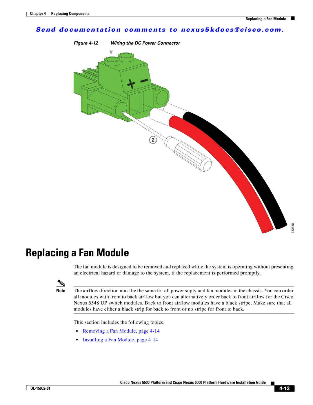
Wiring a DC Power Connector
Replacing a Fan Module
Removing a Fan Module, Installing a Fan Module,
Removing a Fan Module
Installing a Fan Module
14 Installing a Fan Module in a Cisco Nexus 5548 Chassis
15 Installing a Fan Module in a Cisco Nexus 5020 Chassis
Replacing Components
OL-15902-01
General Requirements for Cabinets and Racks
Cabinet and Rack Requirements
Requirements Specific to Perforated Cabinets
Cable Management Guidelines
Description Specification
Switch Specifications
Environmental Specifications
Property Cisco Nexus 5596 Switch Cisco Nexus 5548 Switch
Property Cisco Nexus 5020 Switch Cisco Nexus 5010 Switch
AC Power Supply Properties Specification
Expansion Module Specifications
Power Specifications
Specifications for the Cisco Nexus 5596 Power Supply
DC Power Supply Properties Specification
Specifications for the Cisco Nexus 5548 Power Supply
Specifications for the Cisco Nexus 5010 Power Supply
Specifications for the Cisco Nexus 5020 Power Supplies
Description Short Range
Transceiver Specifications
Description Short Wavelength
Parameter Symbol Minimum Maximum Unit
OL-15902-01
Console Cable
Cable and Port Specifications
Console Port
Cable RJ-45 Connector Pinouts
Signal Name P1, P1-45 Pins P2, DB-9 Pins
Pin Signal
Supported Power Cords and Plugs
Length
Description Feet Meters Illustration
CAB-9K10A-IT
CAB-9K10A-AU
VSCC15
CAB-9K10A-SW
CAB-N5K6A-NA
SS10A
Jumper Power Cord
Figure C-16 CAB-C13-C14-JMPR, Jumper Power Cord
LEDs
Chassis and Module LED Descriptions
Component
Status Description
Power Supply Condition Green Amber
Conditions Indicated by the Power Supply LEDs
Link State LED State
Port LEDs
Ethernet Port LEDs
Ethernet and Fibre Channel LEDs
Snmp Traps
Overview
Switch Operation Best Practices
Switch Hardware Best Practices
Power Supply Conditions
Installation Best Practices
Power Supply Condition Power LED Status Fail LED Status
Cisco Nexus 5000 Series Hardware Installation Guide
Cisco Nexus 5596UP and 5596T Switch Accessory Kit
Accessory Kits
Cisco Nexus 5010 Switch Accessory Kit
Cisco Nexus 5020 Switch Accessory Kit
OL-15902-02-xx
Cisco Nexus 5000 Series Hardware Installation Guide
Site Preparation Checklist
Site Planning and Maintenance Records
Task No Planning Activity Verified By Time Date
Contact and Site Information
Slot Module Type Module Serial Number Supervisor
Chassis and Module Information
Numerics
IN-2
IN-3
IN-4