Chapter 1 Overview
Cisco Nexus 5500 Platform Switches
Se n d d o c u m e n t a t i o n c o m m e n t s t o n ex u s 5 k d o c s @ c i s c o . c o m .
1 | Internal | 4 | Network management port |
|
|
|
|
2 | Link LED (left LED) | 5 | Console port |
|
|
|
|
3 | Activity LED (right LED) |
|
|
|
|
|
|
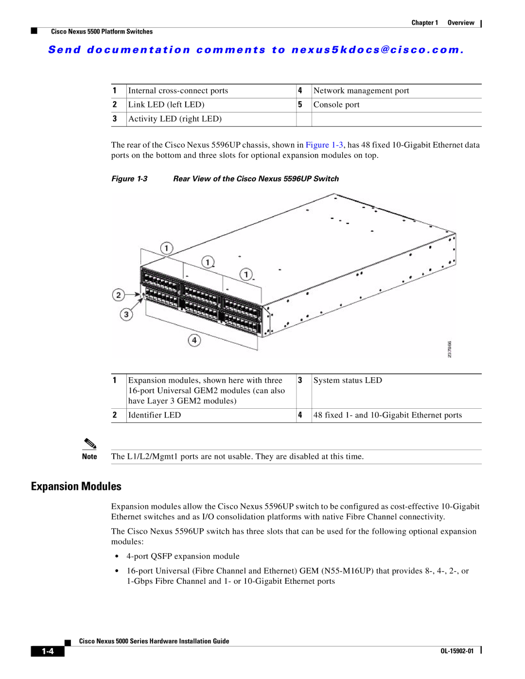
The rear of the Cisco Nexus 5596UP chassis, shown in Figure
Figure 1-3 Rear View of the Cisco Nexus 5596UP Switch
1 | Expansion modules, shown here with three | 3 | System status LED |
|
|
| |
| have Layer 3 GEM2 modules) |
|
|
|
|
|
|
2 | Identifier LED | 4 | 48 fixed 1- and |
|
|
|
|
Note The L1/L2/Mgmt1 ports are not usable. They are disabled at this time.
Expansion Modules
Expansion modules allow the Cisco Nexus 5596UP switch to be configured as
The Cisco Nexus 5596UP switch has three slots that can be used for the following optional expansion modules:
•
•
Cisco Nexus 5000 Series Hardware Installation Guide
| ||
|