Hughes Installation | Configuration and Connections |
|
|
|
|
6.Plug the
______ Secure all of the connector screws.
7.Plug the (4 or 5) BNC connectors from one end of the
BNCs on the Hughes panel. See cable diagram in Figure
____________ If installing the Hughes HJT 100/200, you must also follow the special setup
instructions on page 4.
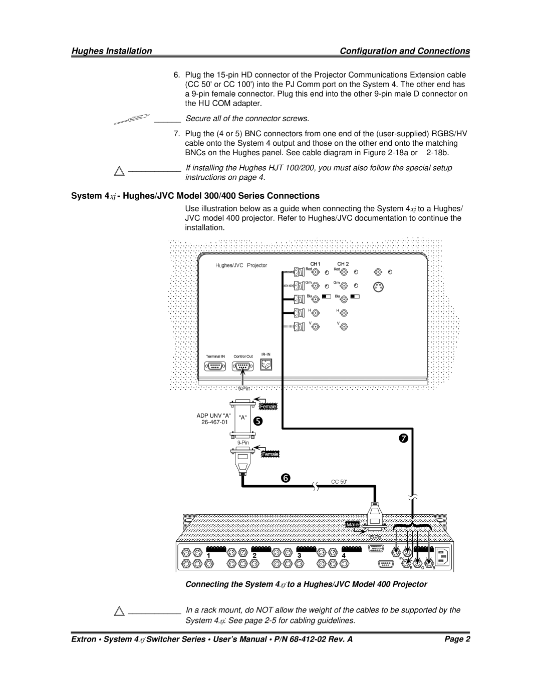
System 4xi - Hughes/JVC Model 300/400 Series Connections
Use illustration below as a guide when connecting the System 4xi to a Hughes/ JVC model 400 projector. Refer to Hughes/JVC documentation to continue the installation.
ADP UNV "A" | "A" | |
|
Connecting the System 4xi to a Hughes/JVC Model 400 Projector
![]() ____________ In a rack mount, do NOT allow the weight of the cables to be supported by the
____________ In a rack mount, do NOT allow the weight of the cables to be supported by the
System 4xi. See page
Extron • System 4xi Switcher Series • User’s Manual • P/N | Page 2 |