
RCP 2000 specifications
The Extron RCP 2000 is a prominent tool in the realm of control systems, designed to enhance user experience in various environments, including educational institutions, corporate settings, and large venues. This remote control panel is engineered for streamlined operation of audio-visual equipment, serving as an indispensable component in managing multimedia presentations.One of the main features of the RCP 2000 is its intuitive interface. Equipped with a backlit, tactile keypad, users can easily find and operate functions even in low-light settings. The ergonomic layout provides quick access to essential controls, such as volume adjustments, source selection, and macro commands, ensuring a user-friendly experience. The inclusion of customizable buttons allows for flexibility, enabling users to tailor the panel to their specific needs.
Another notable characteristic is its support for a wide range of audiovisual technologies. The RCP 2000 is compatible with Extron's extensive line of products and integrates seamlessly with other equipment, facilitating a cohesive system. This compatibility is further enriched by the device’s ability to support IP-based control, allowing for remote monitoring and programming, which is crucial for managing complex AV systems across multiple locations.
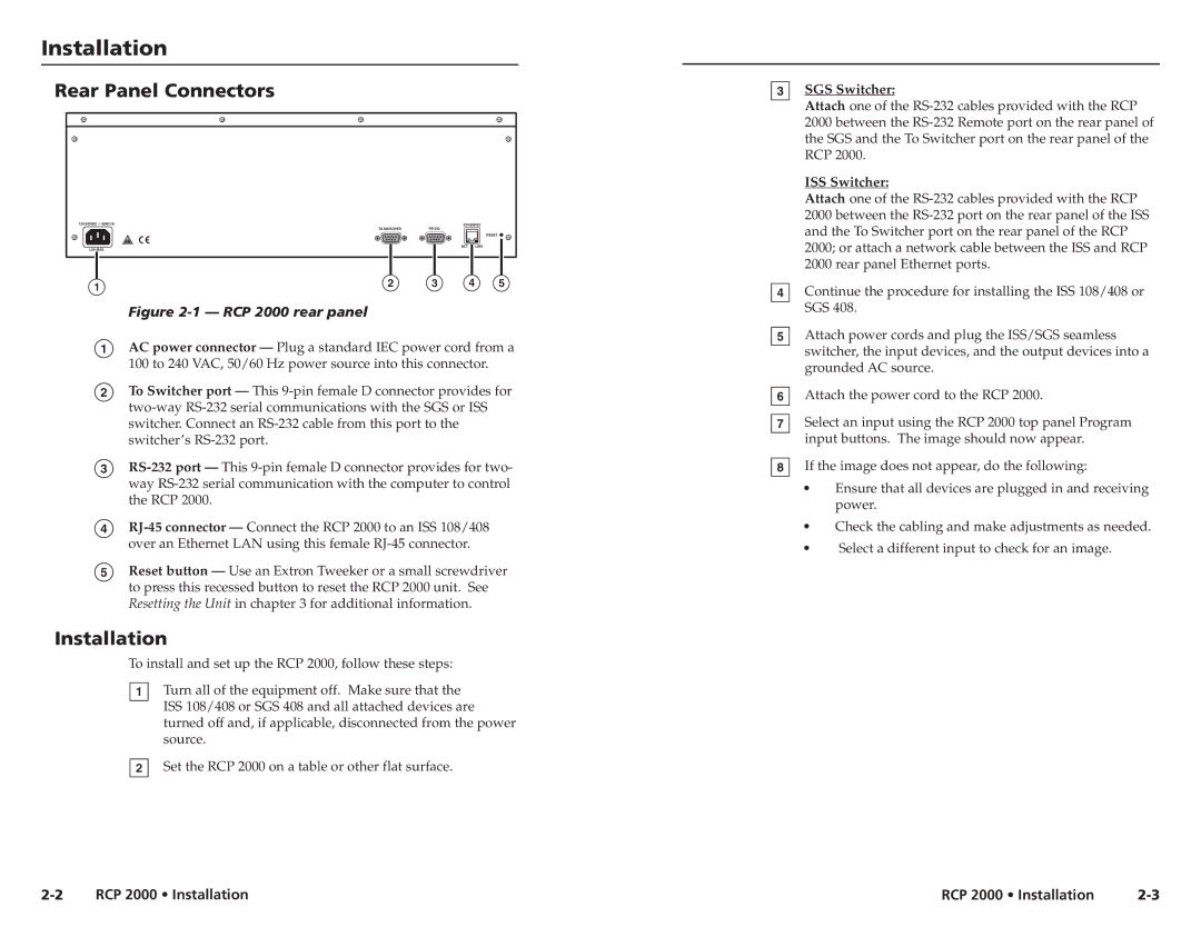
The RCP 2000 also features robust connectivity options, including Ethernet for network integration and RS-232 ports for direct control of hardware devices. This versatility enhances its functionality and ensures compatibility with many modern AV systems. Additionally, the panel supports multiple control protocols, making it adaptable to varied environments and distinct user preferences.
In terms of build quality, the Extron RCP 2000 maintains a high standard. It is constructed from durable materials, designed to withstand daily usage while maintaining its aesthetic appeal. Its compact design allows for easy installation, whether mounted on walls or placed on tables, making it a practical option for space-constrained areas.
In summary, the Extron RCP 2000 stands out with its user-friendly interface, extensive compatibility with audiovisual technologies, and robust construction. These features make it an ideal choice for efficient AV management, ensuring that users can focus on delivering impactful presentations without the hassle of complex control systems.