Operation, cont’d
Tip (+)
![]() Sleeve (
Sleeve (![]() )
) ![]()
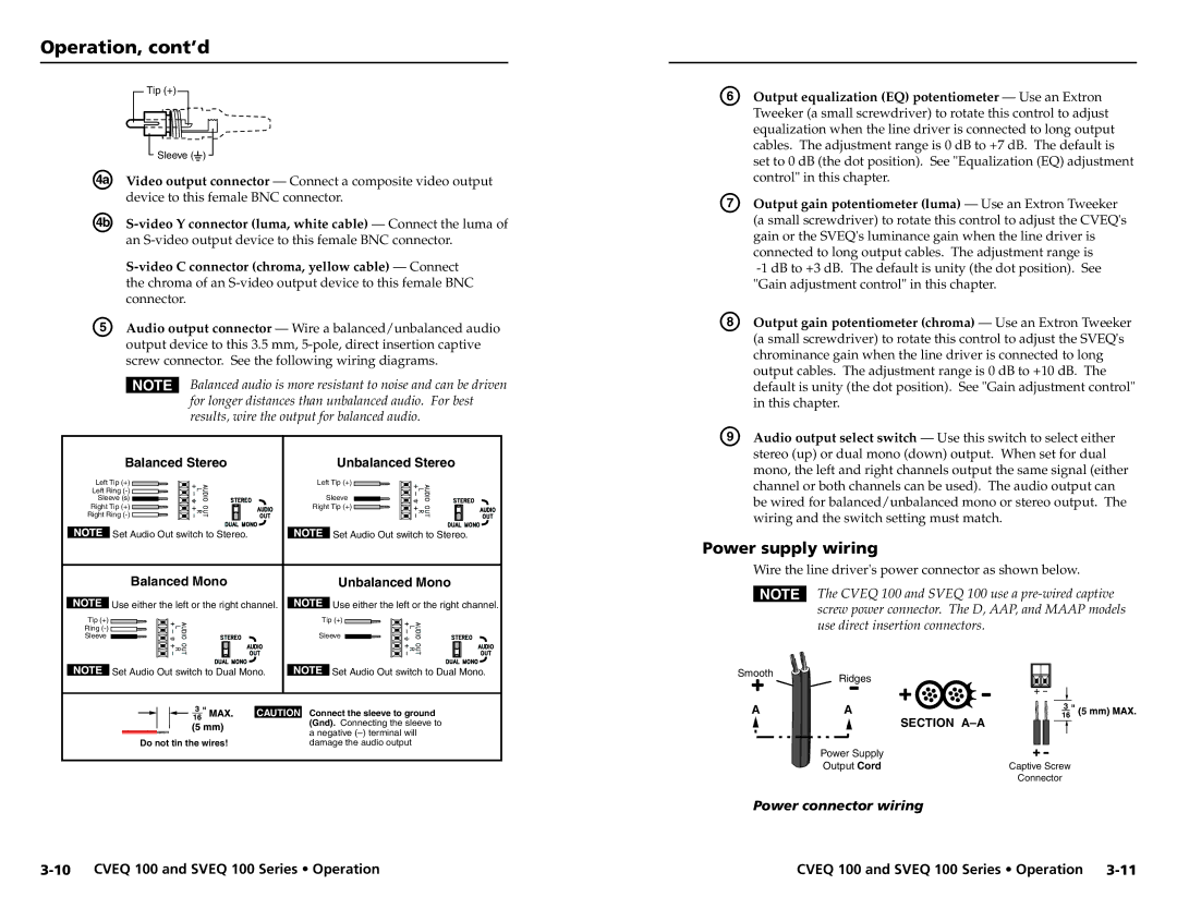
ÜVideo output connector — Connect a composite video output device to this female BNC connector.
Á
E | Audio output connector — Wire a balanced/unbalanced audio |
| output device to this 3.5 mm, |
| screw connector. See the following wiring diagrams. |
NBalanced audio is more resistant to noise and can be driven for longer distances than unbalanced audio. For best results, wire the output for balanced audio.
Balanced Stereo | Unbalanced Stereo |
Left Tip (+) | Left Tip (+) |
Left Ring |
|
Sleeve (s) | Sleeve |
Right Tip (+) | Right Tip (+) |
Right Ring |
|
Set Audio Out switch to Stereo. | Set Audio Out switch to Stereo. |
Balanced Mono | Unbalanced Mono |
Use either the left or the right channel. | Use either the left or the right channel. |
Tip (+) | Tip (+) |
Ring |
|
Sleeve | Sleeve |
Set Audio Out switch to Dual Mono. | Set Audio Out switch to Dual Mono. |
| CAUTION Connect the sleeve to ground |
| (Gnd). Connecting the sleeve to |
| a negative |
Do not tin the wires! | damage the audio output |
F | Output equalization (EQ) potentiometer — Use an Extron |
| Tweeker (a small screwdriver) to rotate this control to adjust |
| equalization when the line driver is connected to long output |
| cables. The adjustment range is 0 dB to +7 dB. The default is |
| set to 0 dB (the dot position). See "Equalization (EQ) adjustment |
| control" in this chapter. |
G | Output gain potentiometer (luma) — Use an Extron Tweeker |
| (a small screwdriver) to rotate this control to adjust the CVEQ's |
| gain or the SVEQ's luminance gain when the line driver is |
| connected to long output cables. The adjustment range is |
| |
| "Gain adjustment control" in this chapter. |
H | Output gain potentiometer (chroma) — Use an Extron Tweeker |
| (a small screwdriver) to rotate this control to adjust the SVEQ's |
| chrominance gain when the line driver is connected to long |
| output cables. The adjustment range is 0 dB to +10 dB. The |
| default is unity (the dot position). See "Gain adjustment control" |
| in this chapter. |
I | Audio output select switch — Use this switch to select either |
| stereo (up) or dual mono (down) output. When set for dual |
| mono, the left and right channels output the same signal (either |
| channel or both channels can be used). The audio output can |
| be wired for balanced/unbalanced mono or stereo output. The |
| wiring and the switch setting must match. |
Power supply wiring
Wire the line driver's power connector as shown below.
NThe CVEQ 100 and SVEQ 100 use a
Smooth ![]()
![]() Ridges
Ridges
A | A | 3 | 5 |
| |||
|
| SECTION | |
|
|
| |
| Power Supply |
|
|
| Output Cord | Captive Screw |
|
|
| Connector |
|
Power connector wiring
CVEQ 100 and SVEQ 100 Series • Operation |