Operation, cont’d
CPower supply voltage polarity is critical. Incorrect voltage polarity can damage the power supply and the line driver. Identify the power cord negative lead by the ridges on the side of the cord.
To verify the polarity before connection, plug in the power supply with no load and check the output with a voltmeter.
WThe two power cord wires must be kept separate while the power supply is plugged in. Remove power before wiring.
NDo not tin the power supply leads before installing in the direct insertion connector. Tinned wires are not as secure in the connectors and could be pulled out.
Gain adjustment control
The gain control adjusts picture brightness by compensating for signal amplitude loss caused by cable resistance. To adjust the output gain, view the display while using a small,
CVEQ 100 Series | SVEQ 100 Series |
NThe gain control is a potentiometer with a mechanical stop at the high and the low end. After you have reached the high or low end of the adjustment, no change is apparent on the display. The default is unity (the dot position)
You can judge the adjustment visually by viewing the display. For a more precise setting use an oscilloscope or a waveform monitor connected to the far end of the output cable, and adjust the gain so that the level at the waveform monitor is 100 IRE.
Equalization (EQ) adjustment control
The equalization control adjusts the output level and peaking to get a sharp picture. This adjustment changes the level and peaking of the output signal to compensate for capacitance caused by up to 1000 feet (300 meters) of Extron MHR cable.
This control produces an equalization adjustment ranging from 0 dB to + 7 dB (CVEQ and luma of SVEQ).
CVEQ 100 Series | SVEQ 100 Series |
Use a small,
NThe EQ control is a potentiometer with a mechanical stop at the high and the low end. After you have reached the high or low end of the adjustment, no change is apparent on the display. The default is set to 0 dB (the dot position).
Replacing the Decora Faceplate (CVEQ 100 D and SVEQ 100 D)
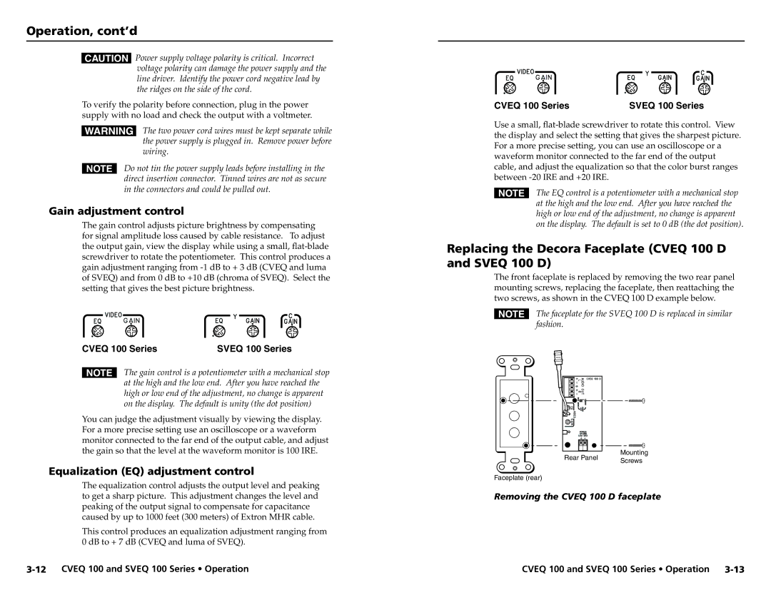
The front faceplate is replaced by removing the two rear panel mounting screws, replacing the faceplate, then reattaching the two screws, as shown in the CVEQ 100 D example below.
NThe faceplate for the SVEQ 100 D is replaced in similar fashion.
|
|
|
|
|
|
|
| Mounting | |
|
|
|
|
|
|
|
| ||
|
|
|
|
|
|
|
| ||
|
|
|
|
|
|
|
| ||
|
|
|
|
|
|
|
| ||
|
|
|
|
|
|
|
| ||
|
|
|
|
|
|
|
| ||
|
|
|
|
|
|
|
| ||
|
|
|
|
|
|
|
| ||
|
|
|
|
|
|
|
| ||
|
|
|
|
|
|
|
| ||
|
|
|
|
|
|
|
| ||
Rear Panel | |||||||||
Screws | |||||||||
|
|
|
|
|
|
|
| ||
Faceplate (rear)
Removing the CVEQ 100 D faceplate
CVEQ 100 and SVEQ 100 Series • Operation |