Installation, cont’d
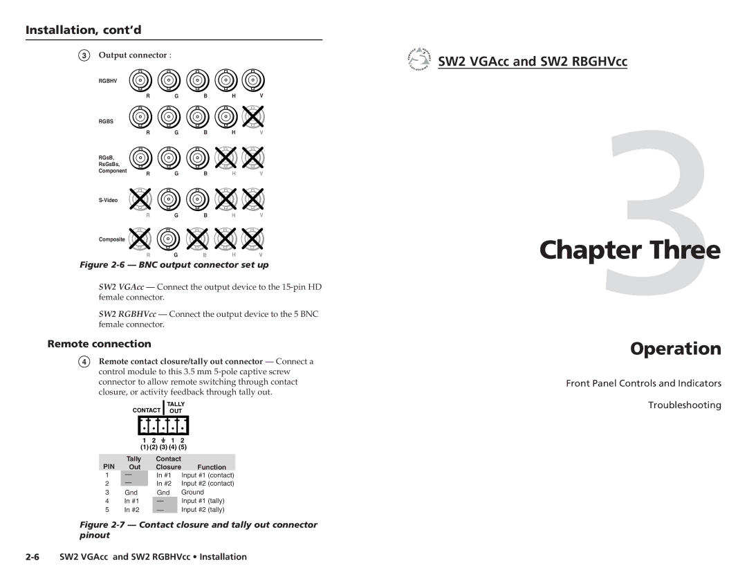
3Output connector :
RGBHV |
|
|
|
|
|
| R | G | B | H | V |
RGBS |
|
|
|
|
|
| R | G | B | H | V |
RGsB, |
|
|
|
|
|
RsGsBs, |
|
|
|
|
|
Component | R | G | B | H | V |
| |||||
|
|
|
|
| |
| R | G | B | H | V |
Composite |
|
|
|
|
|
| R | G | B | H | V |
Figure 2-6 — BNC output connector set up
SW2 VGAcc — Connect the output device to the
SW2 RGBHVcc — Connect the output device to the 5 BNC female connector.
Remote connection
4Remote contact closure/tally out connector — Connect a control module to this 3.5 mm
TALLY
CONTACT OUT
| 1 | 2 |
|
| 1 | 2 | ||
|
| |||||||
| (1) (2) (3) (4) (5) | |||||||
|
|
|
|
|
|
|
| |
PIN | Tally |
|
| Contact |
| |||
Out |
|
| Closure | Function | ||||
1 | — |
|
| In #1 Input #1 (contact) | ||||
2 | — |
|
| In #2 Input #2 (contact) | ||||
|
|
| ||||||
3 | Gnd |
|
| Gnd |
| Ground | ||
4 | In #1 |
|
| — |
| Input #1 (tally) | ||
5 | In #2 |
|
| — |
| Input #2 (tally) | ||
Figure 2-7 — Contact closure and tally out connector pinout
2-6 SW2 VGAcc and SW2 RGBHVcc • Installation

 SW2 VGAcc and SW2 RBGHVcc
Chapter3Three
Operation
Front Panel Controls and Indicators
Troubleshooting