TPX 88 and TPX 88 A
68-733-01 Rev. C
Consignes de Sécurité Français
Precautions
Safety Instructions English
Sicherheitsanleitungen Deutsch
TPX 88 Matrix Switcher Quick Start QS-1
Quick Start - TPX Matrix Switchers
Configuration - One or more ties or sets of ties
Installation
QS-2 TPX 88 Matrix Switchers Quick Start
Quick Start - TPX 88 Matrix Switchers, cont’d
Save or recall a preset
Create a tie
Table of Contents
TPX 88 Matrix Switchers Table of Contents
Table of Contents, cont’d
ii TPX 88 Matrix Switchers Table of Contents
Part Numbers
Specifications
Appendix A Reference Information
Button Labels
iv TPX 88 Matrix Switchers Table of Contents
Chapter1One
TPX 88 Twisted Pair Matrix Switchers
About Both TPX Switcher Models About the TPX 88 A Switchers Features
Introduction
About the TPX 88 Manual
1-2 TPX 88 Matrix Switchers Introduction
Introductiontroduction, cont’d
About the TP A/V System
Family
TPX 88 Matrix Switchers Introduction
Extron twisted pair products’ attributes
Model
Extron twisted pair products’ attributes continued
1-4 TPX 88 Matrix Switchers Introduction
Introduction, cont’d
MTP Receivers
Video format
Transmission distances
Recommended transmission ranges at 60 Hz
Maximum ranges
Figure 1-1 - Typical TPX 88 A matrix switcher application
About Both TPX Switcher Models
1-6 TPX 88 Matrix Switchers Introduction
About the TPX 88 A Switchers
1-8 TPX 88 Matrix Switchers Introduction
Features
Figure 1-2 - Audio gain and attenuation
Any input to any or all outputs
Audio from a transmitter in the MTP family cannot be broken away
1-10 TPX 88 Matrix Switchers Introduction
Mounting the Switcher Cabling and Rear Panel Views
Installation
Chapter2Two
Figure 2-1 - Rack mounting a TPX switcher
Installationstallation, cont’d
Mounting the Switcher
2-2 TPX 88 Matrix Switchers Installation
TPX 88 Matrix Switchers Installation
Figure 2-2 - TPX 88 A twisted pair matrix switcher with audio
Cabling and Rear Panel Views
2-4 TPX 88 Matrix Switchers Installation
Installation, cont’d
Remote configuration DIP switches - Set these DIP switches to
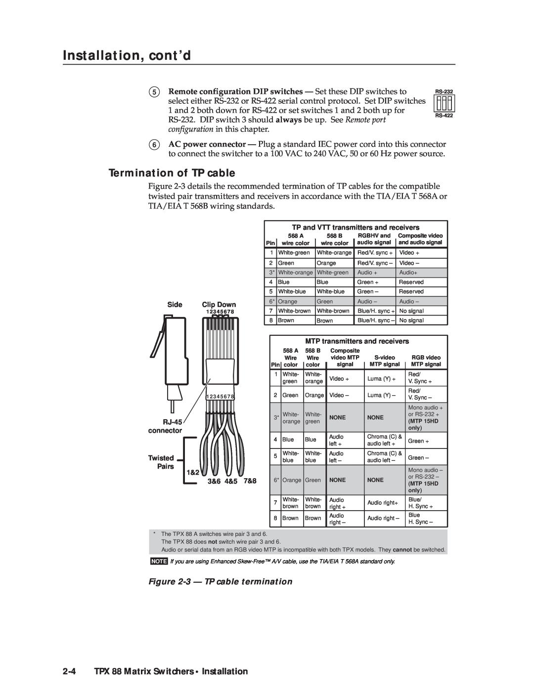
Termination of TP cable
The TPX 88 A switches and processes wire pair 3 and
Cable testing
Equalizing pair skew with Skew Equalizers
2-6 TPX 88 Matrix Switchers Installation
Equalizing pair skew with skew compensation cables
Figure 2-5 - Captive screw connector wiring for audio output
Audio outputs connectors TPX 88 A only
Figure 2-4 - Pair skew equalization
Figure 2-7 - Remote connector
Remote port configuration
Figure 2-6 - Typical audio connectors
2-8 TPX 88 Matrix Switchers Installation
Operation
Front Panel Controls and Indicators Operations Troubleshooting
Chapter3Three
Worksheets
Operationeration, cont’d
Front Panel Controls and Indicators
3-2 TPX 88 Matrix Switchers Operation
Definitions
TPX 88 Matrix Switchers Operation
Control buttons
I/O controls TPX 88 A only
3-4 TPX 88 Matrix Switchers Operation
Operation, cont’d
Audio controls TPX 88 A only
Button icons
Power
Operations
Figure 3-3 - Sample button icons
3-6 TPX 88 Matrix Switchers Operation
I/O grouping
Creating a configuration
Example 1 Creating a set of video and audio ties
3-8 TPX 88 Matrix Switchers Operation
1 2 3 4 5 6 7 1 2 3 4 5 6 7
Figure 3-5 - Select video and audio
Figure 3-9 - Select video only
Figure 3-8 - Press the Enter button
Example 2 Adding a tie to a set of video and audio ties
Figure 3-10 - Select an input
Figure 3-12 - Press the Enter button
3-10 TPX 88 Matrix Switchers Operation
Figure 3-11 - Select the output
Example 3a Removing an audio tie from a set of ties TPX 88 A only
Figure 3-15 - Deselect the output
N 1 2 3 4 5 6 7
Figure 3-14 - Select an input
1 2 3 4 5 6 7
Figure 3-17 - Select an input
3-12 TPX 88 Matrix Switchers Operation
Example 3b Removing a tie from a set of ties TPX 88 only
Press and release the output 4 button figure
Example 4a Viewing ties TPX 88 A only
Viewing a configuration
Figure 3-20 - Select view mode
Figure 3-21 - Select video and audio
3-14 TPX 88 Matrix Switchers Operation
Figure 3-22 - Select an input
Figure 3-24 - Deselect video and select audio to view audio only
Figure 3-23 - Deselect audio to view video only
Figure 3-25 - Press the View button to exit view mode
Figure 3-26 - Select view mode
3-16 TPX 88 Matrix Switchers Operation
Example 4b Viewing ties TPX 88 only
Figure 3-27 - Select an input
Figure 3-29 - Enter save preset mode
Using presets
Example 5 Saving a preset
Figure 3-28 - Press the View button to exit view mode
Figure 3-32 - Select recall preset mode
Figure 3-30 - Select the preset
Example 6 Recalling a preset
3-18 TPX 88 Matrix Switchers Operation
Figure 3-33 - Select the preset
Figure 3-35 - Select audio view and adjust mode
Viewing and adjusting the input audio level TPX 88 A only
Example 7 Viewing and adjusting an input audio level
3-20 TPX 88 Matrix Switchers Operation
B1 2 3 4 5 6 7
Figure 3-37 - Adjust the input audio level
1 2 3 4 5 6 7
Figure 3-36 - Select an input
3-22 TPX 88 Matrix Switchers Operation
Viewing and adjusting the output volume TPX 88 A only
Figure 3-38 - Deselect audio mode
1 2 3 4 5 6 7
Example 8 Viewing and adjusting an output volume level
Figure 3-39 - Select audio view and adjust mode
Figure 3-40 - Select an output
Figure 3-41 - Adjust the output audio volume
3-24 TPX 88 Matrix Switchers Operation
Figure 3-43 - Muting and unmuting outputs
Muting and unmuting the local audio TPX 88 A only
Front panel security lockout executive mode
Figure 3-44 - Toggle the front panel lock on or off
3-26 TPX 88 Matrix Switchers Operation
System reset to factory defaults
Figure 3-45 - System reset
Background illumination
Camera main podium
Troubleshooting
Worksheets
Podium Mic
Podium Mic
Operation, cont’d
Camera main podium
Laptop
Laptop
3-30 TPX 88 Matrix Switchers Operation
3-31
Configuration worksheet
Preset #
Title
3-32 TPX 88 Matrix Switchers Operation
Command/Response Table for SIS Commands
Host-to-Switcher Instructions Switcher-Initiated Messages
Switcher Error Responses Using the Command/Response Table
Chapter4Four
Figure 4-1 - Remote connector pin arrangement
Host-to-Switcher Instructions
Switcher-Initiated Messages
4-2 TPX 88 Matrix Switchers Programmer’s Guide
Switcher Error Responses
TPX 88 Matrix Switchers Programmer’s Guide
4-4 TPX 88 Matrix Switchers Programmer’s Guide
Using the Command/Response Table
Symbol Definitions
Programmer’s Guide, cont’d
ASCII Command
Command/Response Table for SIS Commands
Command
Response
ASCII Command
Command/response table for SIS commands Cont’d
4-6 TPX 88 Matrix Switchers Programmer’s Guide
Audio output volume
I/O Grouping
Save, recall and direct write global presets
Resets
Executive mode
View ties, gain, volume, and presets
4-8 TPX 88 Matrix Switchers Programmer’s Guide
Resets continued
Information requests
Chapter5Five
Matrix Switchers Control Program Button-Label Generator
Matrix Software
Using the software
Matrix Switchers Control Program
Installing the software
5-2 TPX 88 Matrix Switchers Matrix Software
TPX 88 Matrix Switchers Matrix Software
Figure 5-1 - Extron Matrix Switcher+ Control Program window blank
Figure 5-2 - Sample program window complete
Matrix Software, cont’d
Firmware upgrade
5-4 TPX 88 Matrix Switchers Matrix Software
Figure 5-3 - Open window
File menu
Windows buttons, drop boxes, and trash
Windows menus
Tools menu
Preferences menu
5-6 TPX 88 Matrix Switchers Matrix Software
Figure 5-4 - Ties shown as crosspoints
Using emulation mode
Using the help system
Button-Label Generator
5-8 TPX 88 Matrix Switchers Matrix Software
Figure 5-5 - Extron’s Button-Label Generator window
AAppendix A
Specifications Part Numbers Button Labels
Reference Information
ReferenceInformation,co t’d
Specifications
A-2 TPX 88 Matrix Switchers Reference Information
Video
TPX 88 Matrix Switchers Reference Information
Control/Remote - switcher
General
A-4 TPX 88 Matrix Switchers Reference Information
Twisted Pair Matrix Switcher part numbers
Optional accessories
Reference Information, cont’d
RJ-45 connectors
Skew compensation cable
A-6 TPX 88 Matrix Switchers Reference Information
Installing labels in the matrix switcher’s buttons
Button Labels
Figure A-1 - Button label blanks
A-8 TPX 88 Matrix Switchers Reference Information