TPX 88 and TPX 88 A
68-733-01 Rev. C
Precautions
Safety Instructions English
Consignes de Sécurité Français
Sicherheitsanleitungen Deutsch
Quick Start - TPX Matrix Switchers
Configuration - One or more ties or sets of ties
TPX 88 Matrix Switcher Quick Start QS-1
Installation
Quick Start - TPX 88 Matrix Switchers, cont’d
Save or recall a preset
QS-2 TPX 88 Matrix Switchers Quick Start
Create a tie
Table of Contents
TPX 88 Matrix Switchers Table of Contents
Table of Contents, cont’d
ii TPX 88 Matrix Switchers Table of Contents
Specifications
Appendix A Reference Information
Part Numbers
Button Labels
iv TPX 88 Matrix Switchers Table of Contents
TPX 88 Twisted Pair Matrix Switchers
About Both TPX Switcher Models About the TPX 88 A Switchers Features
Chapter1One
Introduction
1-2 TPX 88 Matrix Switchers Introduction
Introductiontroduction, cont’d
About the TPX 88 Manual
About the TP A/V System
TPX 88 Matrix Switchers Introduction
Extron twisted pair products’ attributes
Family
Model
1-4 TPX 88 Matrix Switchers Introduction
Introduction, cont’d
Extron twisted pair products’ attributes continued
MTP Receivers
Transmission distances
Recommended transmission ranges at 60 Hz
Video format
Maximum ranges
About Both TPX Switcher Models
Figure 1-1 - Typical TPX 88 A matrix switcher application
1-6 TPX 88 Matrix Switchers Introduction
About the TPX 88 A Switchers
Features
1-8 TPX 88 Matrix Switchers Introduction
Figure 1-2 - Audio gain and attenuation
Any input to any or all outputs
Audio from a transmitter in the MTP family cannot be broken away
1-10 TPX 88 Matrix Switchers Introduction
Installation
Mounting the Switcher Cabling and Rear Panel Views
Chapter2Two
Installationstallation, cont’d
Mounting the Switcher
Figure 2-1 - Rack mounting a TPX switcher
2-2 TPX 88 Matrix Switchers Installation
Figure 2-2 - TPX 88 A twisted pair matrix switcher with audio
TPX 88 Matrix Switchers Installation
Cabling and Rear Panel Views
Installation, cont’d
Remote configuration DIP switches - Set these DIP switches to
2-4 TPX 88 Matrix Switchers Installation
Termination of TP cable
The TPX 88 A switches and processes wire pair 3 and
Cable testing
2-6 TPX 88 Matrix Switchers Installation
Equalizing pair skew with Skew Equalizers
Equalizing pair skew with skew compensation cables
Audio outputs connectors TPX 88 A only
Figure 2-5 - Captive screw connector wiring for audio output
Figure 2-4 - Pair skew equalization
Remote port configuration
Figure 2-6 - Typical audio connectors
Figure 2-7 - Remote connector
2-8 TPX 88 Matrix Switchers Installation
Front Panel Controls and Indicators Operations Troubleshooting
Chapter3Three
Operation
Worksheets
Front Panel Controls and Indicators
3-2 TPX 88 Matrix Switchers Operation
Operationeration, cont’d
Definitions
TPX 88 Matrix Switchers Operation
Control buttons
3-4 TPX 88 Matrix Switchers Operation
Operation, cont’d
I/O controls TPX 88 A only
Audio controls TPX 88 A only
Power
Operations
Button icons
Figure 3-3 - Sample button icons
3-6 TPX 88 Matrix Switchers Operation
I/O grouping
Creating a configuration
3-8 TPX 88 Matrix Switchers Operation
1 2 3 4 5 6 7 1 2 3 4 5 6 7
Example 1 Creating a set of video and audio ties
Figure 3-5 - Select video and audio
Figure 3-8 - Press the Enter button
Example 2 Adding a tie to a set of video and audio ties
Figure 3-9 - Select video only
Figure 3-10 - Select an input
3-10 TPX 88 Matrix Switchers Operation
Figure 3-11 - Select the output
Figure 3-12 - Press the Enter button
Example 3a Removing an audio tie from a set of ties TPX 88 A only
N 1 2 3 4 5 6 7
Figure 3-14 - Select an input
Figure 3-15 - Deselect the output
1 2 3 4 5 6 7
3-12 TPX 88 Matrix Switchers Operation
Example 3b Removing a tie from a set of ties TPX 88 only
Figure 3-17 - Select an input
Press and release the output 4 button figure
Viewing a configuration
Example 4a Viewing ties TPX 88 A only
Figure 3-20 - Select view mode
3-14 TPX 88 Matrix Switchers Operation
Figure 3-21 - Select video and audio
Figure 3-22 - Select an input
Figure 3-23 - Deselect audio to view video only
Figure 3-24 - Deselect video and select audio to view audio only
Figure 3-25 - Press the View button to exit view mode
3-16 TPX 88 Matrix Switchers Operation
Example 4b Viewing ties TPX 88 only
Figure 3-26 - Select view mode
Figure 3-27 - Select an input
Using presets
Example 5 Saving a preset
Figure 3-29 - Enter save preset mode
Figure 3-28 - Press the View button to exit view mode
Figure 3-30 - Select the preset
Example 6 Recalling a preset
Figure 3-32 - Select recall preset mode
3-18 TPX 88 Matrix Switchers Operation
Figure 3-33 - Select the preset
Viewing and adjusting the input audio level TPX 88 A only
Example 7 Viewing and adjusting an input audio level
Figure 3-35 - Select audio view and adjust mode
3-20 TPX 88 Matrix Switchers Operation
Figure 3-37 - Adjust the input audio level
1 2 3 4 5 6 7
B1 2 3 4 5 6 7
Figure 3-36 - Select an input
Viewing and adjusting the output volume TPX 88 A only
3-22 TPX 88 Matrix Switchers Operation
Figure 3-38 - Deselect audio mode
Example 8 Viewing and adjusting an output volume level
Figure 3-39 - Select audio view and adjust mode
1 2 3 4 5 6 7
Figure 3-40 - Select an output
Figure 3-41 - Adjust the output audio volume
3-24 TPX 88 Matrix Switchers Operation
Muting and unmuting the local audio TPX 88 A only
Front panel security lockout executive mode
Figure 3-43 - Muting and unmuting outputs
Figure 3-44 - Toggle the front panel lock on or off
System reset to factory defaults
Figure 3-45 - System reset
3-26 TPX 88 Matrix Switchers Operation
Background illumination
Troubleshooting
Worksheets
Camera main podium
Podium Mic
Operation, cont’d
Camera main podium
Podium Mic
Laptop
Camera main podium
3-30 TPX 88 Matrix Switchers Operation
Configuration worksheet
Preset #
3-31
Title
3-32 TPX 88 Matrix Switchers Operation
Host-to-Switcher Instructions Switcher-Initiated Messages
Switcher Error Responses Using the Command/Response Table
Command/Response Table for SIS Commands
Chapter4Four
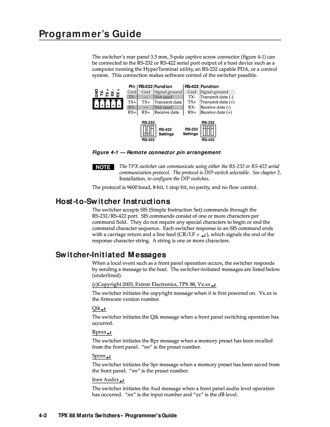
Host-to-Switcher Instructions
Switcher-Initiated Messages
Figure 4-1 - Remote connector pin arrangement
4-2 TPX 88 Matrix Switchers Programmer’s Guide
Switcher Error Responses
TPX 88 Matrix Switchers Programmer’s Guide
Using the Command/Response Table
Symbol Definitions
4-4 TPX 88 Matrix Switchers Programmer’s Guide
Programmer’s Guide, cont’d
Command/Response Table for SIS Commands
Command
ASCII Command
Response
Command/response table for SIS commands Cont’d
4-6 TPX 88 Matrix Switchers Programmer’s Guide
ASCII Command
Audio output volume
Save, recall and direct write global presets
Resets
I/O Grouping
Executive mode
4-8 TPX 88 Matrix Switchers Programmer’s Guide
Resets continued
View ties, gain, volume, and presets
Information requests
Matrix Switchers Control Program Button-Label Generator
Chapter5Five
Matrix Software
Matrix Switchers Control Program
Installing the software
Using the software
5-2 TPX 88 Matrix Switchers Matrix Software
Figure 5-1 - Extron Matrix Switcher+ Control Program window blank
TPX 88 Matrix Switchers Matrix Software
Figure 5-2 - Sample program window complete
Firmware upgrade
5-4 TPX 88 Matrix Switchers Matrix Software
Matrix Software, cont’d
Figure 5-3 - Open window
Windows buttons, drop boxes, and trash
Windows menus
File menu
Tools menu
5-6 TPX 88 Matrix Switchers Matrix Software
Preferences menu
Figure 5-4 - Ties shown as crosspoints
Using emulation mode
Using the help system
5-8 TPX 88 Matrix Switchers Matrix Software
Button-Label Generator
Figure 5-5 - Extron’s Button-Label Generator window
Specifications Part Numbers Button Labels
AAppendix A
Reference Information
Specifications
A-2 TPX 88 Matrix Switchers Reference Information
ReferenceInformation,co t’d
Video
Control/Remote - switcher
TPX 88 Matrix Switchers Reference Information
General
Twisted Pair Matrix Switcher part numbers
Optional accessories
A-4 TPX 88 Matrix Switchers Reference Information
Reference Information, cont’d
RJ-45 connectors
Skew compensation cable
Installing labels in the matrix switcher’s buttons
A-6 TPX 88 Matrix Switchers Reference Information
Button Labels
Figure A-1 - Button label blanks
A-8 TPX 88 Matrix Switchers Reference Information