Installation and Operation, cont’d
Back of the rack mounting
The YCS SW2 A can also be mounted vertically to the front or rear rack supports, using the optional MBB 100 back of the rack mounting kit (part
Follow these steps to mount the YCS to the rack supports using the back of the rack mounting kit:
1. | If feet were previously attached to the bottom of the YCS, |
| remove them. |
2. | Remove the two screws from one side of the YCS. Retain |
| the screws for possible later reassembly. |
3. | Attach one bracket to the side of the unit, using the longer |
| screws included in the mounting kit (see figure |
Figure 2-4 — Attaching the back of the rack mounting brackets to the YCS SW2 A
4. | Repeat steps 2 and 3 on the other side of the YCS. |
5. | Mount the unit to the rack support, using the two included |
| rack screws. |
MLS103V
12V |
|
|
|
| SW2YCS |
|
|
|
|
| |
.5A | MAX |
|
|
|
|
|
|
|
|
| 2 |
|
| MLS |
|
|
|
|
| 103V |
|
|
|
|
|
|
|
| 1 |
|
|
|
| 12V |
|
|
|
|
| .5A | MAX |
|
|
|
|
| MLS |
|
|
|
|
| 103V |
| 1 | OUTPUT1 |
|
|
|
|
|
|
| 12V | |
|
| 2 |
|
| .5AM |
|
|
| 3 |
|
|
|
|
| 1 | OUTP | |
|
|
|
| ||
|
|
|
|
| 2UT2 |
|
|
|
|
| 3 |
|
|
|
|
| M |
|
|
|
|
| MX32 |
|
|
|
|
| VGAA |
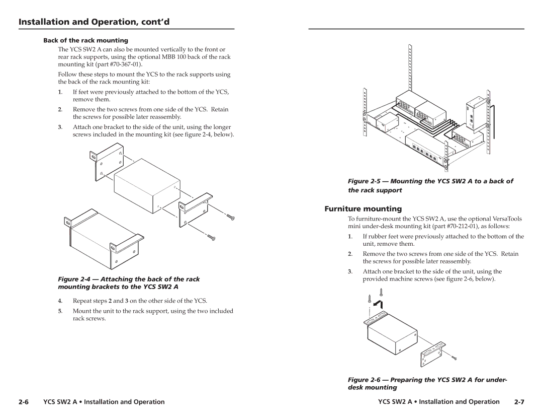
Figure 2-5 — Mounting the YCS SW2 A to a back of the rack support
Furniture mounting
To
1. | If rubber feet were previously attached to the bottom of the |
| unit, remove them. |
2. | Remove the two screws from one side of the YCS. Retain |
| the screws for possible later reassembly. |
3. | Attach one bracket to the side of the unit, using the |
| provided machine screws (see figure |
Figure 2-6 — Preparing the YCS SW2 A for under- desk mounting
YCS SW2 A • Installation and Operation |