Installation and Operation, cont’d
Front Panel Features
| 1 | 2 |
| 3 | 4 |
| 5 | |||||||
| AUTO |
|
|
|
|
| 1 |
|
|
|
|
| 2 | |
| SWITCH |
|
|
|
|
|
|
|
| |||||
|
|
|
|
|
|
|
|
| ||||||
|
|
|
|
|
|
|
|
|
|
|
|
|
| YCS SW2 A |
|
|
|
|
|
|
|
|
|
|
|
|
|
| |
|
|
|
|
|
|
|
|
|
|
|
|
|
| |
| Figure | |||||||||||||
A | Auto Switch LED — This green LED lights when autoswitching | |||||||||||||
| is enabled. When this LED is lit, the Input Selection buttons | |||||||||||||
| are disabled (although their indicator LEDs continue to light to | |||||||||||||
| indicate which input has been selected). See “Autoswitching,” | |||||||||||||
| earlier in this chapter, for the procedure to set up autoswitching. | |||||||||||||
B | Input 1 Selection button — Press this button to select input 1, | |||||||||||||
| composite video. |
|
|
|
|
|
|
|
|
|
| |||
C | Input 1 indicator LED — This green LED lights when input 1 | |||||||||||||
| has been selected. |
|
|
|
|
|
|
|
|
|
| |||
D | Input 2 Selection button — Press this button to select input 2, | |||||||||||||
|
|
|
|
|
|
|
|
|
|
|
|
|
| |
E | Input 2 indicator LED — This green LED lights when input 2 | |||||||||||||
| has been selected. |
|
|
|
|
|
|
|
|
|
| |||
NThe YCS SW2 A does not have
Enabling Black and White Mode for NTSC
In order to detect NTSC signals that are black and white only, the YCS must be placed in black and white mode. To enable this mode, use the small jumper that is provided within the unit.
The jumper temporarily connects two pins on the YCS internal board. To make this connection, fit the jumper onto the two pins (“closed” position). To break the connection, remove the jumper from one of the pins (“open” position).
To use the jumper to enable black and white mode,
1. | Remove power from the YCS. |
2. | Using an Extron Tweeker or other small screwdriver, |
| remove the four case screws on the sides of the unit. |
3. | Gently slide the top cover up and away from the lower |
| housing. |
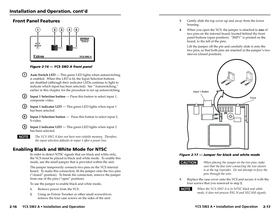
4. | When you open the YCS, the jumper is attached to one of |
| two pins on the internal board, located behind the front |
panel buttons (open position). “JMP1” is printed on the board, to the left of the pins.
Lift the jumper off the pin and carefully slide it onto the two pins, so that both pins are inserted in the jumper’s two sleeves (closed position).
Input 1 Button
Front
| CR5 |
JMP1 | J26 |
| |
SW1 |
|
Figure 2-17 — Jumper for black and white mode
CWhen placing the jumper on the two pins, make sure that the fine wire connecting the two sleeves is at the top (outside). Do not attempt to force the pins through the wire.
5. Replace the case cover onto the YCS and secure it with the four screws that you removed in step 2.
NWhen the YCS SW2 A is in NTSC black and white mode, it does not process PAL N and SECAM signals.
YCS SW2 A • Installation and Operation |