Installation and Operation, cont’d
Cable Input from
Sources (AV control)
Rear Panel Features
Bottom Plate
FRONT
Cable Access | REAR |
Hole |
| 1 | 2 |
| INPUTS | OUTPUT |
|
| 1 |
POWER | VIDEO |
|
12V |
| 2 |
0.4A MAX |
|
3 4 5
INPUTS | OUTPUT |
1 | 2 |
L | L | REMOTE |
|
| |
|
| CONTACT |
1 2
RR ![]()
AUDIOAUTO-SW
| Cable Output |
| to Projector |
Figure | |
7. | Connect the cables to the YCS, its power supply, and |
| any additional devices/power supplies that you want to |
| mount. |
8. | Pull excess cable back into the ceiling. Feed the device(s) |
| output cables to the projector through the cable access hole |
| and out through the bottom of the pipe. |
8.Insert the lugs on the bottom
| plate into the slots on the top | Slots (4) |
| plate and slide the bottom plate |
|
| into position. |
|
9. | Lock the top and bottom plates |
|
| together with the security screws |
|
10. | Pass the AC power cord through | Lugs (4) |
| ||
| the slot at the rear of the top |
|
| plate. |
|
11. Reattach the front and rear plates.
| 10 | 9 | 8 | 7 | 6 |
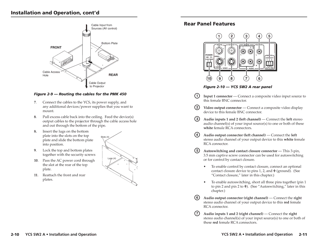
| Figure | ||||
A | Input 1 connector — Connect a composite video input source to | ||||
| this female BNC connector. |
| |||
B | Video output connector — Connect a composite video display | ||||
| device to this female BNC connector. | ||||
C | Audio inputs 1 and 2 (left channel) — Connect the left stereo | ||||
| audio channel(s) of your input source(s) to one or both of these | ||||
| white female RCA connectors. |
| |||
D | Audio output connector (left channel) — Connect the left | ||||
| stereo audio channel of your output device to this white female | ||||
RCA connector.
E Autoswitching and contact closure connector — This 3-pin,
3.5mm captive screw connector can be used for autoswitching or for control by contact closure.
• To enable control by contact closure, connect an optional
| contact closure device to pins 1, 2, and |
| (ground). (See | ||
|
| ||||
|
| ||||
| “Contact closure,” later in this chapter.) | ||||
| • To enable autoswitching, short all three pins together (pin 1 | ||||
| to pin 2 and pin 2 to |
| ). (See “Autoswitching,” later in this | ||
|
| ||||
|
| ||||
| chapter.) | ||||
F | Audio output connector (right channel) — Connect the right | ||||
| stereo audio channel of your output device to this red female | ||||
| RCA connector. | ||||
G | Audio inputs 1 and 2 (right channel) — Connect the right | ||||
| stereo audio channel(s) of your input source(s) to one or both of | ||||
| these red female RCA connectors. | ||||
YCS SW2 A • Installation and Operation |