Debugger General Information
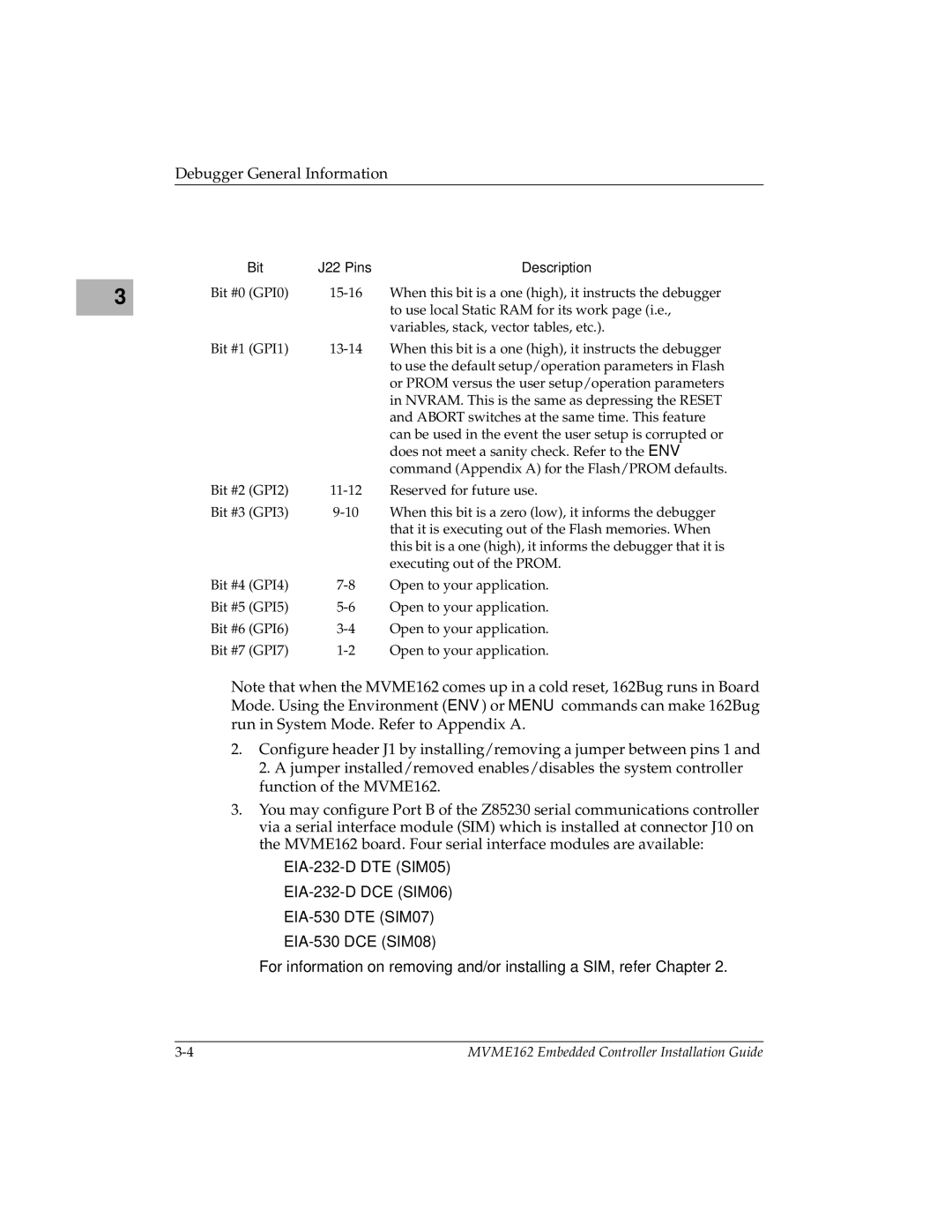
| Bit | J22 Pins | Description |
3 | Bit #0 (GPI0) | When this bit is a one (high), it instructs the debugger | |
|
|
| to use local Static RAM for its work page (i.e., |
|
|
| variables, stack, vector tables, etc.). |
| Bit #1 (GPI1) | When this bit is a one (high), it instructs the debugger | |
|
|
| to use the default setup/operation parameters in Flash |
|
|
| or PROM versus the user setup/operation parameters |
|
|
| in NVRAM. This is the same as depressing the RESET |
|
|
| and ABORT switches at the same time. This feature |
|
|
| can be used in the event the user setup is corrupted or |
|
|
| does not meet a sanity check. Refer to the ENV |
|
|
| command (Appendix A) for the Flash/PROM defaults. |
| Bit #2 (GPI2) | Reserved for future use. | |
| Bit #3 (GPI3) | When this bit is a zero (low), it informs the debugger | |
|
|
| that it is executing out of the Flash memories. When |
|
|
| this bit is a one (high), it informs the debugger that it is |
|
|
| executing out of the PROM. |
| Bit #4 (GPI4) | Open to your application. | |
| Bit #5 (GPI5) | Open to your application. | |
| Bit #6 (GPI6) | Open to your application. | |
| Bit #7 (GPI7) | Open to your application. |
Note that when the MVME162 comes up in a cold reset, 162Bug runs in Board Mode. Using the Environment (ENV) or MENU commands can make 162Bug run in System Mode. Refer to Appendix A.
2.Configure header J1 by installing/removing a jumper between pins 1 and 2. A jumper installed/removed enables/disables the system controller function of the MVME162.
3.You may configure Port B of the Z85230 serial communications controller via a serial interface module (SIM) which is installed at connector J10 on the MVME162 board. Four serial interface modules are available:
–
–
–
–
For information on removing and/or installing a SIM, refer Chapter 2.
MVME162 Embedded Controller Installation Guide |
