MVME162IG/D2
MVME162
Restricted Rights Legend
Preface
Page
Safety Summary Safety Depends On You
Page
Overview
Introduction
Document Title Motorola Publication Number
Related Documentation
Introduction
MVME162 Embedded Controller Installation Guide
Requirements
Features
MVME162 Specifications
Specifications
Characteristics Specifications
Special Considerations for Elevated Temperature Operation
Manual Terminology
MVME162 Block Diagram
Block Diagram
Functional Description
Front Panel Switches and Indicators
MC68040 or MC68LC040 MPU
Data Bus Structure
No-VMEbus-Interface Option
MC68xx040 Cache
Dram Options
Memory Options
Sram Options
About the Battery
Eprom and Flash
Battery Backed Up RAM and Clock
Interfaces
VMEbus Interface and VMEchip2
Serial Communications Interface
MVME162 Serial Port
MVME162 Serial Port
Optional LAN Ethernet Interface
IndustryPack IP Interfaces
Scsi Termination
Optional Scsi Interface
Watchdog Timer
Programmable Tick Timers
Local Bus Timeout
Local Resources
Memory Maps
Connectors
Local Bus Arbiter
Local Bus Arbitration Priority
Normal Address Range
Local Bus Memory Map
Local Bus Memory Map
MVME162 Embedded Controller Installation Guide
Address Range Device Port Width Size
Local Bus I/O Devices Memory Map
MVME162 Embedded Controller Installation Guide
VMEbus Memory Map
VMEbus Accesses to the Local Bus
VMEbus Short I/O Memory Map
Board Level Hardware Description
Hardware Preparation
Unpacking Instructions
SIM Selection
Hardware Preparation
Serial Interface Module Part Numbers
Configuration Part Number Model Standard
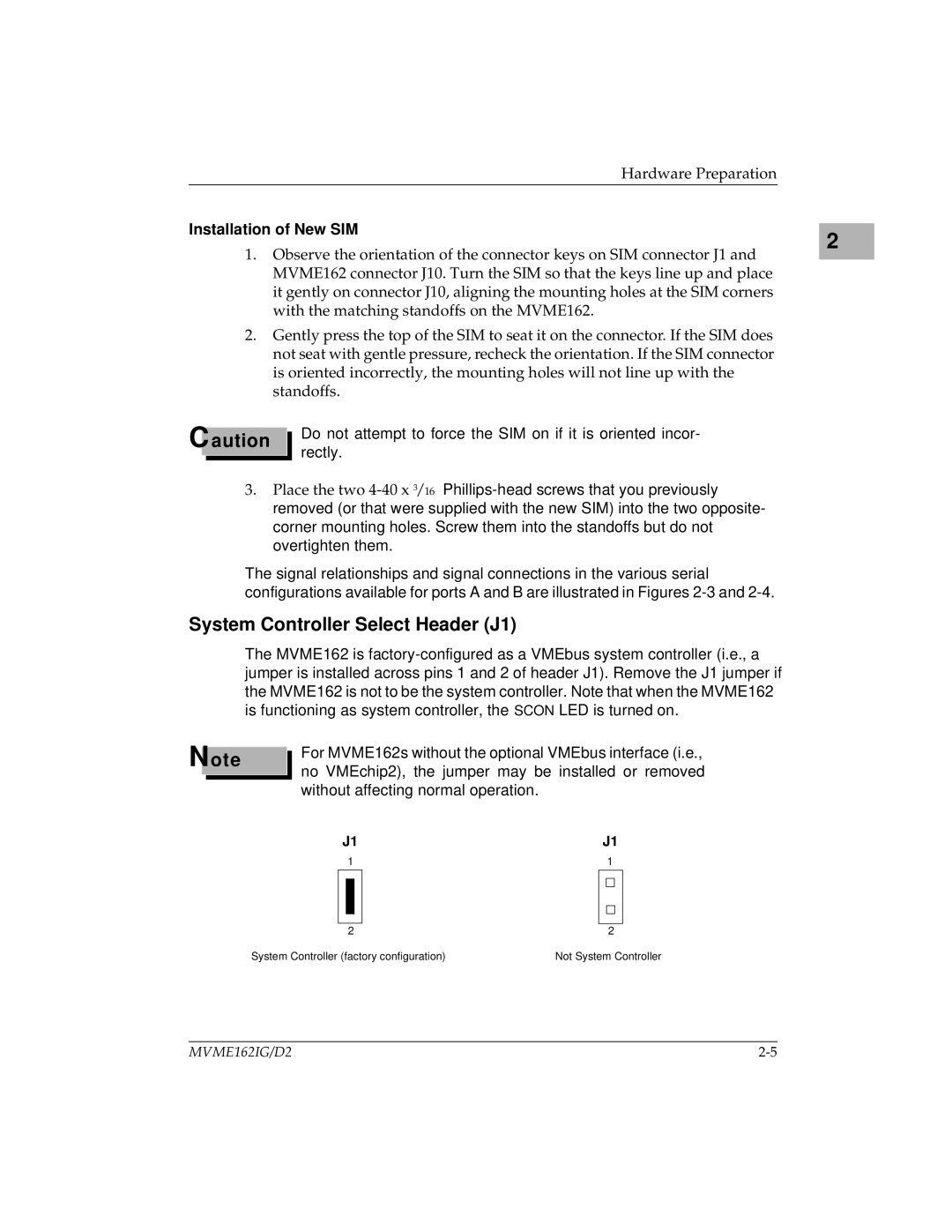
System Controller Select Header J1
Installation of New SIM
J12
Clock Select Header J12 for Serial Port
Eprom Size Select Header J21
Sram Battery Backup Source Select Header J20
J22
General Purpose Readable Jumpers Header J22
IP Installation on the MVME162
Installation Instructions
MVME162 Module Installation
System Considerations
MVME162 Embedded Controller Installation Guide
MVME162 EIA-232-D Connection Diagram, MVME712M Sheet 1
MVME162 EIA-232-D Connection Diagram, MVME712M Sheet 2
MVME162 EIA-232-D Connection Diagram, MVME712M Sheet 3
MVME162 EIA-232-D Connection Diagram, MVME712M Sheet 4
MVME162 EIA-232-D Connection Diagram, MVME712M Sheet 5
MVME162 EIA-232-D Connection Diagram, MVME712M Sheet 6
SIM07
MVME162 EIA-530 Connection Diagram Sheet 1
Hardware Preparation and Installation
MVME162 EIA-530 Connection Diagram Sheet 2
MVME162 EIA-232-D Connection Diagram, MVME712A/AM/-12/-13
Sheet 1
MVME162 EIA-23-D Connection Diagram, MVME712A/AM/-12/-13
Sheet 2
MVME162 EIA-232-D Connection Diagram, MVME712A/AM/-12/-13
Sheet 3
MVME162 EIA-232-D Connection Diagram, MVME712A/AM/-12/-13
Sheet 4
Hardware Preparation and Installation
Description of 162Bug
Overview of M68000 Firmware
MVME162 Embedded Controller Installation Guide
162Bug Implementation
Installation and Startup
Debugger General Information
Bit J22 Pins Description
Ote
Autoboot
ROMboot
Restarting the System
Network Boot
Abort
Reset
Break
SYSFAIL* Assertion/Negation
Memory Requirements
MPU Clock Speed Calculation
Terminal Input/Output Control
DEL
Blocks Versus Sectors
Disk I/O Support
Device Probe Function
Disk I/O via 162Bug Commands
IOI Input/Output Inquiry
IOP Physical I/O to Disk
BH Bootstrap and Halt
BO Bootstrap Operating System
Disk I/O via 162Bug System Calls
IOC I/O Control
Default 162Bug Controller and Device Parameters
Network I/O Support
Disk I/O Error Codes
Intel 82596 LAN Coprocessor Ethernet Driver
UDP/IP Protocol Modules
Network Boot Control Module
Bootp Protocol Module
Network I/O Error Codes
RARP/ARP Protocol Modules
Multiprocessor Control Register Mpcr Method
Multiprocessor Support
Mpar
Gcsr Method
Diagnostic Facilities
Manufacturing Test Process
Debugger
Entering Debugger Command Lines
Italic strings
Syntactic Variables
Data Type Base Identifier Examples
Expression as a Parameter
String Numeric Value Literal Hexadecimal
Address Formats
Address as a Parameter
Expression Result In Hex
Format Example Description
Debugger Address Parameter Formats
Relative addresses are limited to 1MB 5 digits, regardless
Offset Registers
Range of the closest offset register
162BugMD 1327CDI
Port Numbers
Calling System Utilities from User Programs
Entering and Debugging Programs
Preserving the Debugger Operating Environment
Hardware Functions
162Bug Vector Table and Workspace
Exception Vectors Used by 162Bug
Exception Vectors Used by 162Bug
Vector Exception 162Bug Facility Offset
Using 162Bug Target Vector Table
Creating a New Vector Table
Buildx MOVEC.L VBR,A0
162Bug Generalized Exception Handler
162BugMD A7&30
Integer Data Types
Floating Point Support
Floating Point Data Types
Double Precision Real
Single Precision Real
Extended Precision Real
Scientific Notation
Packed Decimal Real
Debugger Commands
162Bug Debugger Command Set
162Bug Debugger Command Set
Norb
Cnfg IM
Configure Board Information Block
Configure and Environment Commands
ENV D
Set Environment to Bug/Operating System
ENV Parameter and Options Default Meaning of Default
Table A-1. ENV Command Parameters
Ffdffffc
Nvram
Memory Requirements section
Base Address of Dynamic Memory
Slave Ending Address #1
Master Starting Address #1
Master Starting Address #3
Table A-1. ENV Command Parameters
Bits Register Address
Configuring the IndustryPacks
FFFBC016
First Second Controller Type
Disk/Tape Controller Modules Supported
Address
Cisc Embedded Controllers -- 7 Devices
Disk/Tape Controller Default Configurations
MVME320 -- 4 Devices
Controller LUN Address Device LUN Device Type
MVME327A -- 9 Devices
MVME323 -- 4 Devices
MVME350 -- 1 Device
MVME328 -- 14 Devices
IOT Command Parameters for Supported Floppy Types
Disk/Tape Controller Data
Controller Interface Type
Network Controller Modules Supported
Address Type
Network Controller Data
Numerics
Symbols
IN-2
IN-3
IN-4
IN-5
IN-6
Scsi LED
Sysfail