1
Board Level Hardware Description
–VMEbus interface to local bus (A24/A32,
D8/D16/D32 (D8/D16/D32/D64 BLT) (BLT = Block Transfer)
–Local bus to VMEbus interface (A16/A24/A32, D8/D16/D32)
–VMEbus interrupter
–VMEbus interrupt handler
–Global CSR for interprocessor communications
–DMA for fast local memory - VMEbus transfers (A16/A24/A32, D16/D32 (D16/D32/D64 BLT)
❏Switches and
–Two pushbutton switches (ABORT and RESET)
–Eight LEDs (FAIL, STAT, RUN, SCON, LAN, FUSE, SCSI, and VME)
Specifications
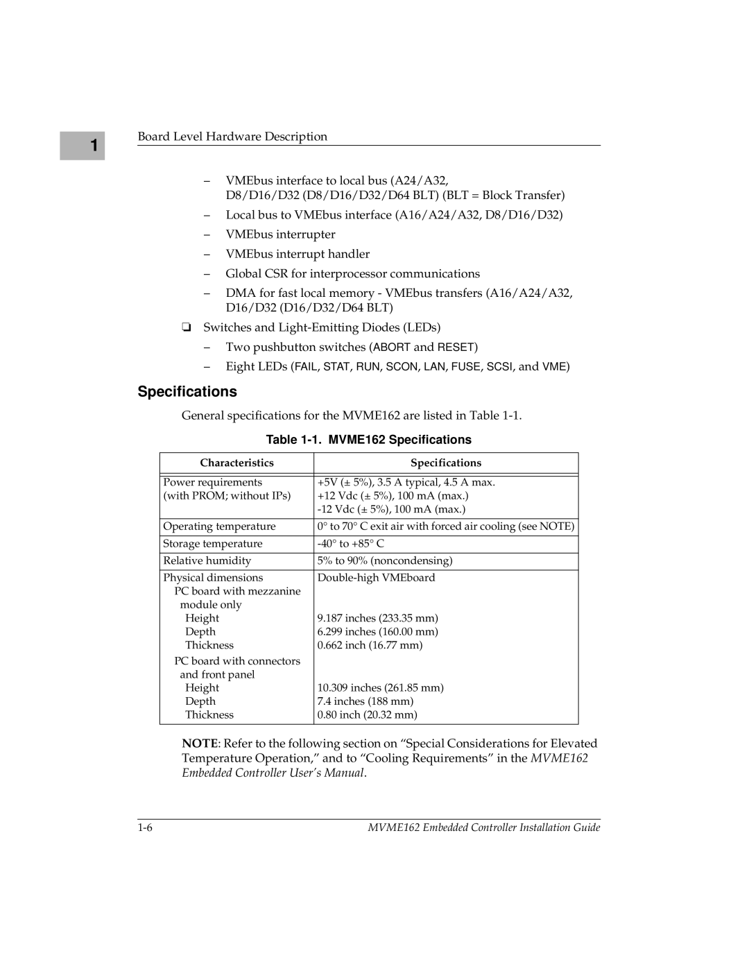
General specifications for the MVME162 are listed in Table
Table 1-1. MVME162 Specifications
Characteristics | Specifications | |
|
| |
|
|
|
Power requirements | +5V (± 5%), 3.5 A typical, 4.5 A max. | |
(with PROM; without IPs) | +12 Vdc (± 5%), 100 mA (max.) | |
| ||
|
| |
Operating temperature | 0° to 70° C exit air with forced air cooling (see NOTE) | |
|
| |
Storage temperature | ||
|
| |
Relative humidity | 5% to 90% (noncondensing) | |
|
| |
Physical dimensions | ||
PC board with mezzanine |
|
|
module only |
|
|
Height | 9.187 inches (233.35 mm) | |
Depth | 6.299 inches (160.00 mm) | |
Thickness | 0.662 inch (16.77 mm) | |
PC board with connectors |
|
|
and front panel |
|
|
Height | 10.309 inches (261.85 mm) | |
Depth | 7.4 inches (188 mm) | |
Thickness | 0.80 inch (20.32 mm) | |
|
|
|
NOTE: Refer to the following section on “Special Considerations for Elevated Temperature Operation,” and to “Cooling Requirements” in the MVME162 Embedded Controller User’s Manual.
MVME162 Embedded Controller Installation Guide |
