Hardware Preparation and Installation
2
Table 2-1. Serial Interface Module Part Numbers
EIA | Configuration | Part Number | Model | |
Standard | Number | |||
|
| |||
|
|
|
| |
|
|
|
| |
DTE | SIM05 | |||
|
|
|
| |
| DCE | SIM06 | ||
|
|
|
| |
|
|
|
| |
DTE | SIM07 | |||
|
|
|
| |
| DCE | SIM08 | ||
|
|
|
|
39 | 1 |
| J1 |
40 | 2 |
SECONDARY SIDE
10922.00 9403
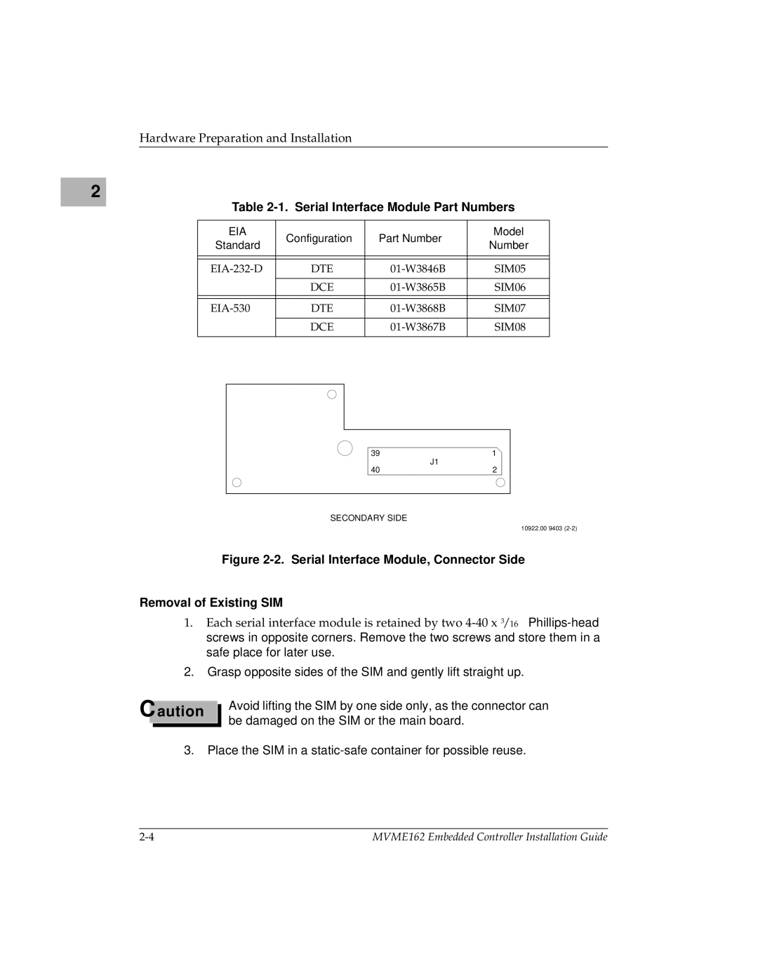
Figure 2-2. Serial Interface Module, Connector Side
Removal of Existing SIM
1.Each serial interface module is retained by two
2.Grasp opposite sides of the SIM and gently lift straight up.
Caution
Avoid lifting the SIM by one side only, as the connector can be damaged on the SIM or the main board.
3.Place the SIM in a
MVME162 Embedded Controller Installation Guide |