Cooktop & Installation Manual
Model COGB ENGLISH
Gas Connection
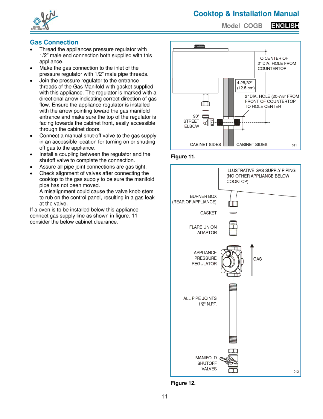
• Thread the appliances pressure regulator with |
1/2” male end connection both supplied with this |
appliance. |
• Make the gas connection to the inlet of the |
pressure regulator with 1/2” male pipe threads. |
• Join the pressure regulator to the entrance |
threads of the Gas Manifold with gasket supplied |
with this appliance. The regulator is marked with a |
directional arrow indicating correct direction of gas |
flow. Ensure the appliance regulator is installed |
with the arrow pointing toward the gas manifold |
entrance and make sure the top of the regulator is |
facing towards the cabinet front, easily accessible |
through the cabinet doors. |
• Connect a manual |
in an accessible location for turning on or shutting |
off gas to the appliance. |
• Install a coupling between the regulator and the |
shutoff valve to complete the connection. |
• Assure all pipe joint connections are gas tight. |
90°
STREET ELBOW
CABINET SIDES
Figure 11.
TO CENTER OF
2" DIA. HOLE FROM COUNTERTOP
(12.5 cm)
2" DIA. HOLE
CABINET SIDES | 011 |
• Check alignment of valves after connecting the |
cooktop to the gas supply to be sure the manifold |
pipe has not been moved. |
A misalignment could cause the valve knob stem |
to rub on the control panel, resulting in a gas leak |
at the valve.
If a oven is to be installed below this appliance connect gas supply line as shown in figure. 11 consider the below cabinet clearance.
BURNER BOX (REAR OF APPLIANCE)
GASKET
FLARE UNION
ADAPTOR
APPLIANCE
PRESSURE
REGULATOR
ILLUSTRATIVE GAS SUPPLY PIPING (NO OTHER APPLIANCE BELOW COOKTOP)
GAS
ALL PIPE JOINTS 1/2" N.P.T.
MANIFOLD |
|
SHUTOFF |
|
VALVES | 012 |
|
Figure 12.
11
