GX75.book Seite 11 Freitag, 18. April 2008 11:14 11
GX 75 |
| us |
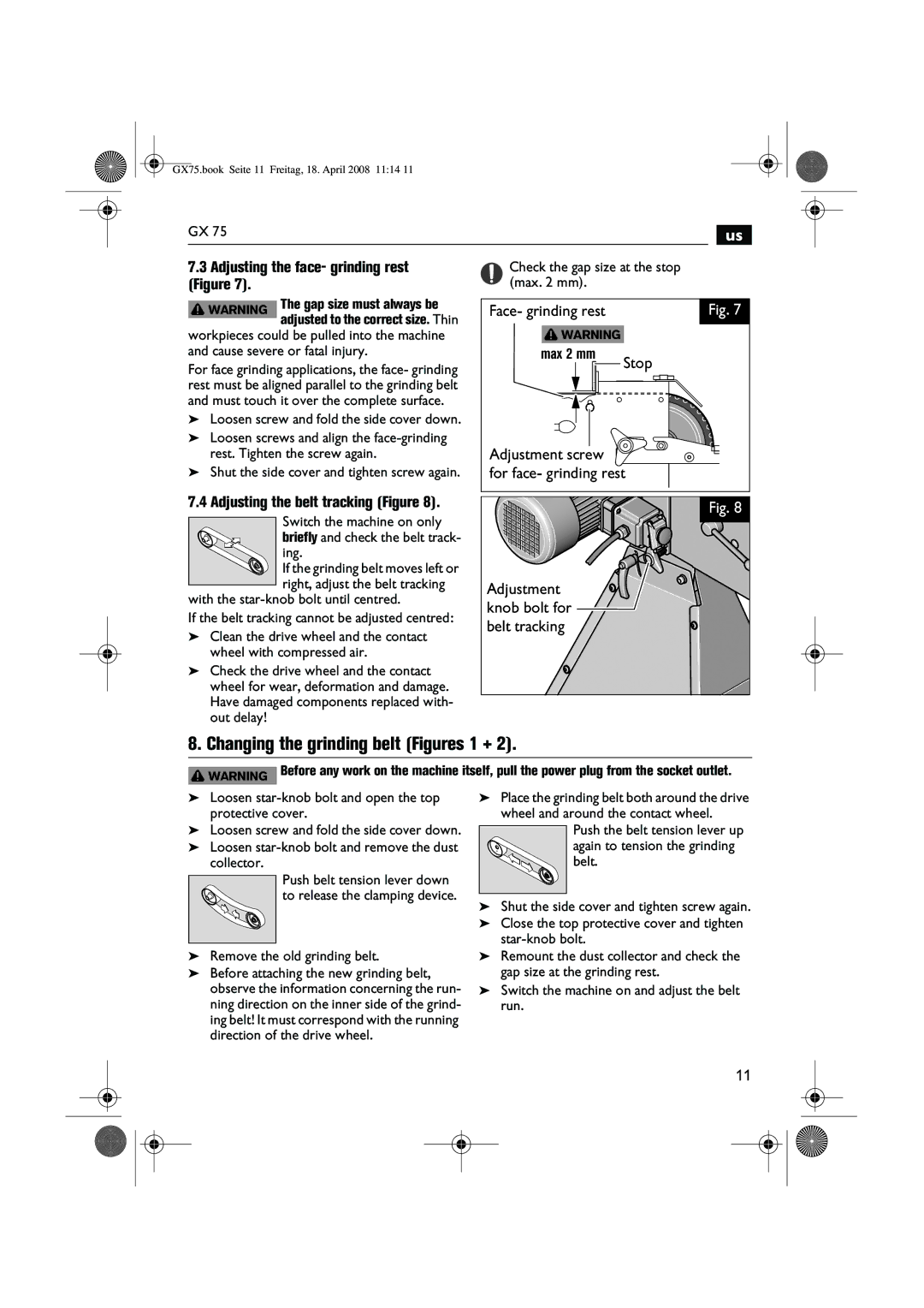
7.3Adjusting the face- grinding rest (Figure 7).
WARNING The gap size must always be adjusted to the correct size. Thin
workpieces could be pulled into the machine and cause severe or fatal injury.
For face grinding applications, the face- grinding rest must be aligned parallel to the grinding belt and must touch it over the complete surface.
➤Loosen screw and fold the side cover down.
➤Loosen screws and align the
➤Shut the side cover and tighten screw again.
7.4 Adjusting the belt tracking (Figure 8).
Switch the machine on only ![]()
![]() briefly and check the belt track-
briefly and check the belt track-
ing.
![]() If the grinding belt moves left or right, adjust the belt tracking
If the grinding belt moves left or right, adjust the belt tracking
with the
If the belt tracking cannot be adjusted centred:
➤Clean the drive wheel and the contact wheel with compressed air.
➤Check the drive wheel and the contact wheel for wear, deformation and damage. Have damaged components replaced with- out delay!
Check the gap size at the stop (max. 2 mm).
Face- grinding rest |
| Fig. 7 |
WARNING |
|
|
max 2 mm | Stop |
|
|
| |
Adjustment screw |
|
|
for face- grinding rest |
| |
Fig. 8 |
Adjustment |
knob bolt for |
belt tracking |
8. Changing the grinding belt (Figures 1 + 2).
![]() WARNING Before any work on the machine itself, pull the power plug from the socket outlet.
WARNING Before any work on the machine itself, pull the power plug from the socket outlet.
➤Loosen
➤Loosen screw and fold the side cover down.
➤Loosen
Push belt tension lever down to release the clamping device.
➤Remove the old grinding belt.
➤Before attaching the new grinding belt, observe the information concerning the run- ning direction on the inner side of the grind- ing belt! It must correspond with the running direction of the drive wheel.
➤Place the grinding belt both around the drive wheel and around the contact wheel.
Push the belt tension lever up again to tension the grinding belt.
➤Shut the side cover and tighten screw again.
➤Close the top protective cover and tighten
➤Remount the dust collector and check the gap size at the grinding rest.
➤Switch the machine on and adjust the belt run.
11