Removal and Replacement Procedures
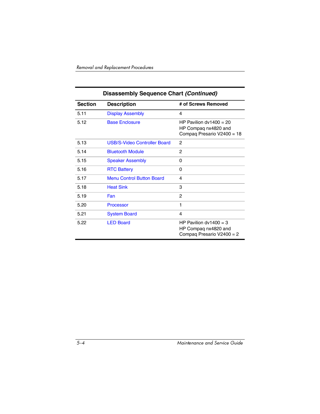
Disassembly Sequence Chart (Continued)
Section | Description | # of Screws Removed |
|
|
|
5.11 | Display Assembly | 4 |
|
|
|
5.12 | Base Enclosure | HP Pavilion dv1400 = 20 |
|
| HP Compaq nx4820 and |
|
| Compaq Presario V2400 = 18 |
|
|
|
5.13 | 2 | |
|
|
|
5.14 | Bluetooth Module | 2 |
|
|
|
5.15 | Speaker Assembly | 0 |
|
|
|
5.16 | RTC Battery | 0 |
|
|
|
5.17 | Menu Control Button Board | 4 |
|
|
|
5.18 | Heat Sink | 3 |
|
|
|
5.19 | Fan | 2 |
|
|
|
5.20 | Processor | 1 |
|
|
|
5.21 | System Board | 4 |
|
|
|
5.22 | LED Board | HP Pavilion dv1400 = 3 |
|
| HP Compaq nx4820 and |
|
| Compaq Presario V2400 = 2 |
|
|
|
Maintenance and Service Guide |