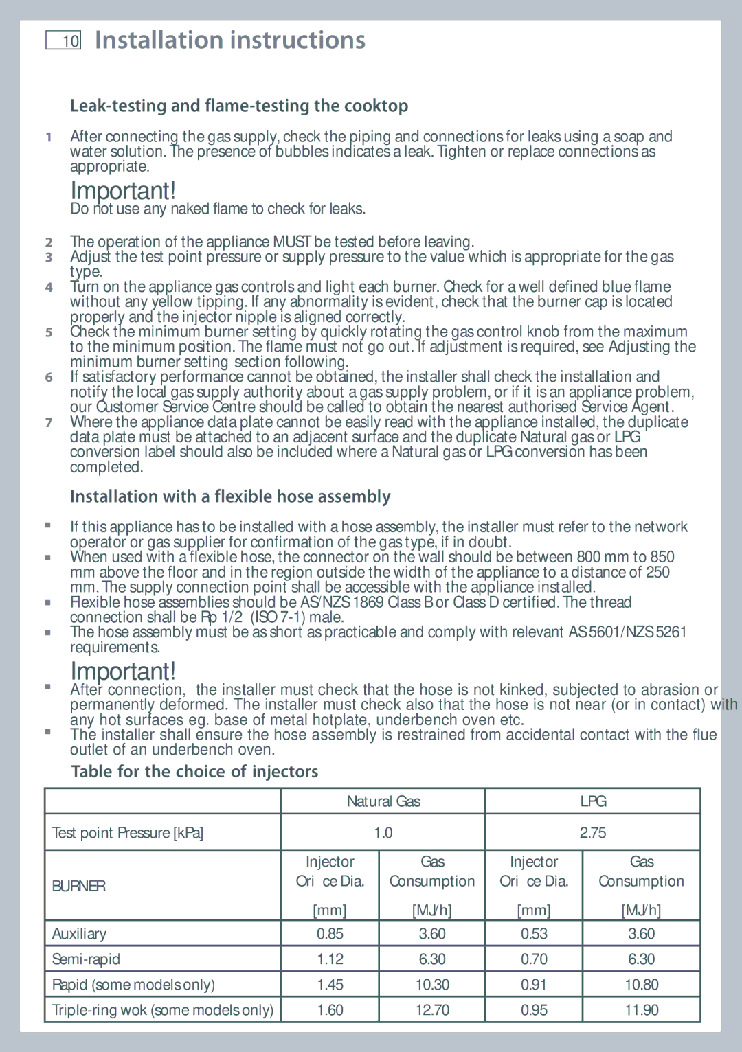
CG905 specifications
Fisher & Paykel CG905 is a modern gas cooktop that embodies a blend of innovative technology and classic craftsmanship. This cooktop is designed for both professional chefs and home cooks, meeting the higher demands of culinary enthusiasts. One of the standout features of the CG905 is its powerful gas burners. It boasts five burners, including a powerful 5.4kW single wok burner that is perfect for high-temperature cooking. The precision of heat control allows for a range of cooking styles, from quick simmering to rapid boiling.Aesthetic appeal is also a strong suit of the CG905. Its sleek, stainless-steel finish not only enhances the look of your kitchen but also ensures durability and easy cleaning. The cooktop features a minimalist design that fits well in various kitchen layouts, providing a contemporary feel while being functional. The ergonomic knob controls are strategically placed for easy access and are designed for precise adjustments, making it easier to switch from high to low heat quickly.
The CG905 incorporates a unique technology known as the Exact Flame feature, which ensures that the flame remains steady at any setting. This contributes significantly to cooking precision, allowing users to achieve perfect results with every meal. Additionally, the cooktop is equipped with a flame failure device, providing an essential safety feature that automatically turns off the gas supply if the flame goes out.
Cleaning the Fisher & Paykel CG905 is made convenient with its removable burner caps and enamel trivets, which can easily be cleaned in the dishwasher. The minimalist design reduces the number of crevices and seams where food debris can hide, making maintenance an easier task.
The CG905 also offers flexibility in installation thanks to its ability to be flush-mounted, which creates a seamless look and integrates beautifully with the kitchen countertop. Furthermore, its gas connection allows for consistent performance and reliability associated with professional-grade cooking appliances.
In summary, the Fisher & Paykel CG905 gas cooktop stands out with its robust performance, sophisticated design, and advanced safety features, making it an optimal choice for anyone looking to elevate their cooking experience at home. With its combination of technology and style, it is an investment that will not only enhance culinary capabilities but also complement the overall aesthetics of any modern kitchen.

