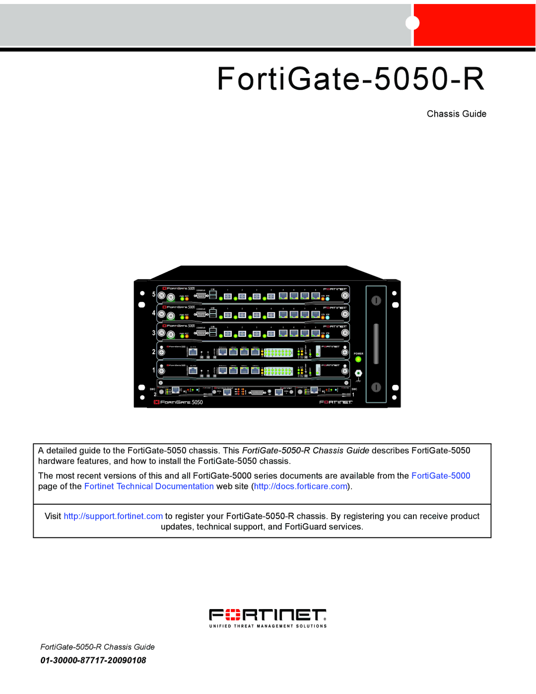
FortiGate-5050-R
Chassis Guide
5 | PWR ACC |
4 | PWR ACC |
3 | PWR ACC |
|
CONSOLE | USB | 1 | 2 | 3 | 4 | 5 | 6 | 7 | 8 |
|
|
|
|
|
|
|
|
|
| STA | IPM |
CONSOLE | USB | 1 | 2 | 3 | 4 | 5 | 6 | 7 | 8 |
|
|
|
|
|
|
|
|
|
| STA | IPM |
CONSOLE | USB | 1 | 2 | 3 | 4 | 5 | 6 | 7 | 8 |
|
|
|
|
|
|
|
|
|
| STA | IPM |
2 | MANAGEMENT | ET H O | SYSTEM | CONSOLE | RS 2 3 2 | RZ E 0 | RZ E 1 | RZ E 2 | E2 E1 | 14 15 | 12 13 | 10 11 | 8 9 | 6 7 | 4 5 | 2 3 | 0 1 | ZRE | CLK OK | EXT INT FLT FLT | SWAPHOT | RESET | LEDMODE | POWER |
|
|
1 | MANAGEMENT | ET H O | SYSTEM | CONSOLE | RS 2 3 2 | RZ E 0 | RZ E 1 | RZ E 2 | E2 E1 | 14 15 | 12 13 | 10 11 | 8 9 | 6 7 | 4 5 | 2 3 | 0 1 | ZRE | CLK OK | EXT INT FLT FLT | SWAPHOT | RESET | LED MODE |
SMC
2
5000SM | ETH0 | Service | RESET | STATUS | Hot Swap | 1 | 5050SAP | 2 | 5000SM | ETH0 | Service | RESET | STATUS | Hot Swap | SMC | ||
ETH0ETH1 | link/Act | ALARM | ETH0ETH1 | link/Act | |||||||||||||
| 10/100 |
|
|
|
|
| SERIAL |
| SERIAL |
| 10/100 |
|
|
|
|
| |
| link/Act |
|
|
|
|
|
|
| link/Act |
|
|
|
|
| 1 | ||
| 10/100 |
|
|
|
|
|
|
|
|
| 10/100 |
|
|
|
|
| |
|
|
|
|
|
|
|
|
|
|
|
|
|
|
|
|
| |
Adetailed guide to the
The most recent versions of this and all
Visit http://support.fortinet.com to register your
updates, technical support, and FortiGuard services.
