Connecting the
FortiGate-5053 power converter tray front and back panel
The front panel of the
Figure 10: Front panel of the FortiGate-5053 power converter tray with one power supply removed
AC Power
LED DC Power
LED
Slot 3 | Slot 2 | Slot 1 |
The LEDs for each installed power supply are visible from the
Table 6:
LED | State | Description |
|
|
|
AC Power | Green | The power supply is connected to AC power. |
|
|
|
| Off | The power supply is not receiving DC power. This can happen if an AC |
|
| cable is not connected, if the power supply is not correctly installed in |
|
| the slot, or if the power supply is not functioning. |
|
|
|
DC Power | Green | The power supply is providing DC power. |
|
|
|
| Off | The power supply is not providing DC power. If the AC power LED is lit |
|
| and the DC power LED is not, the power supply is not functioning |
|
| correctly and should be replaced. This LED can also go off if the power |
|
| supply overheats. If this happens the power supply stops supplying DC |
|
| power. After the power supply cools down in will start supplying DC |
|
| power again and this LED lights. |
|
|
|
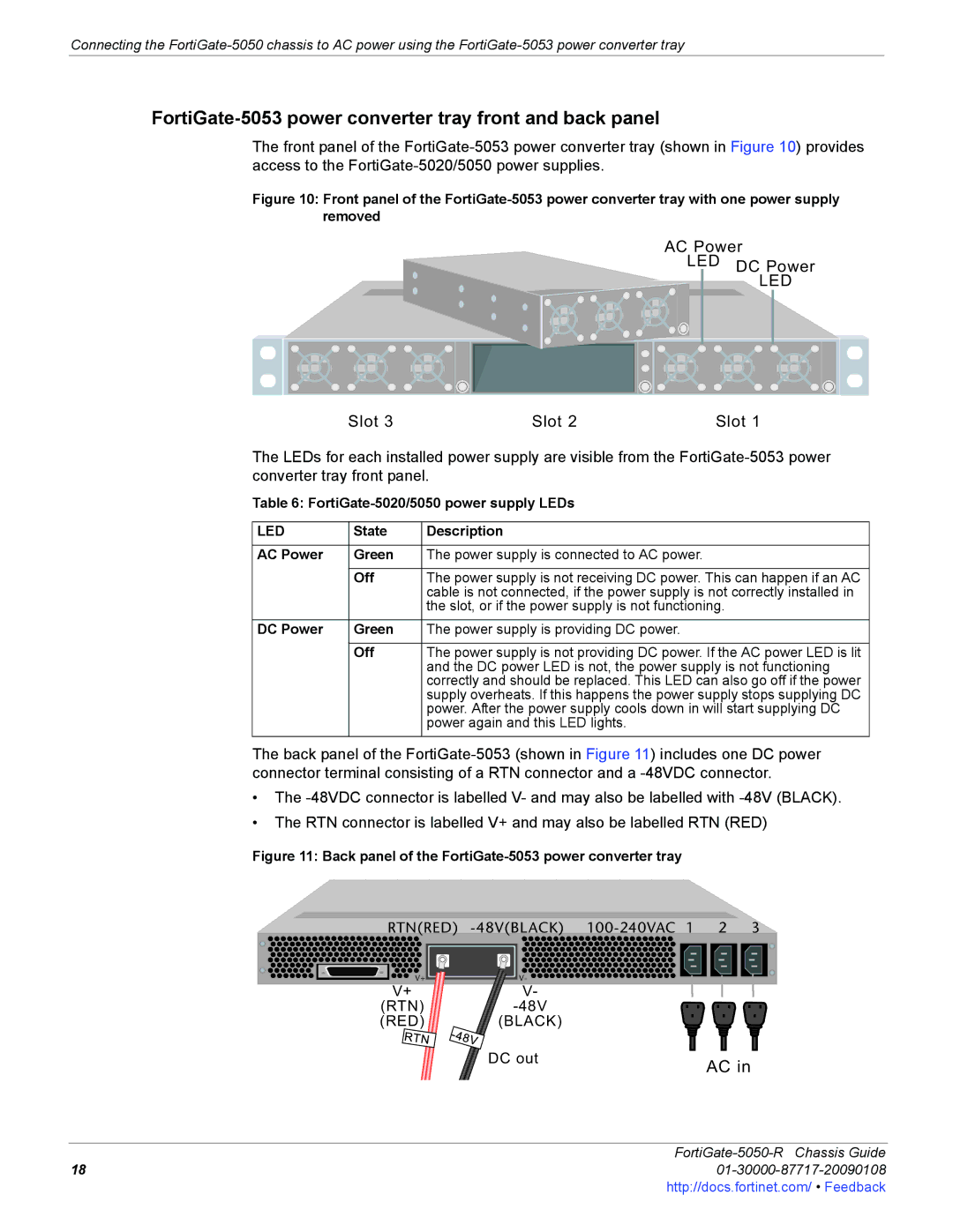
The back panel of the
•The
•The RTN connector is labelled V+ and may also be labelled RTN (RED)
Figure 11: Back panel of the FortiGate-5053 power converter tray
RTN(RED)
V+ | V- |
V+ | V- |
(RTN) | |
(RED) | (BLACK) |
DC out
AC in
FortiGate-5050-R Chassis Guide
1801-30000-87717-20090108http://docs.fortinet.com/ • Feedback