|
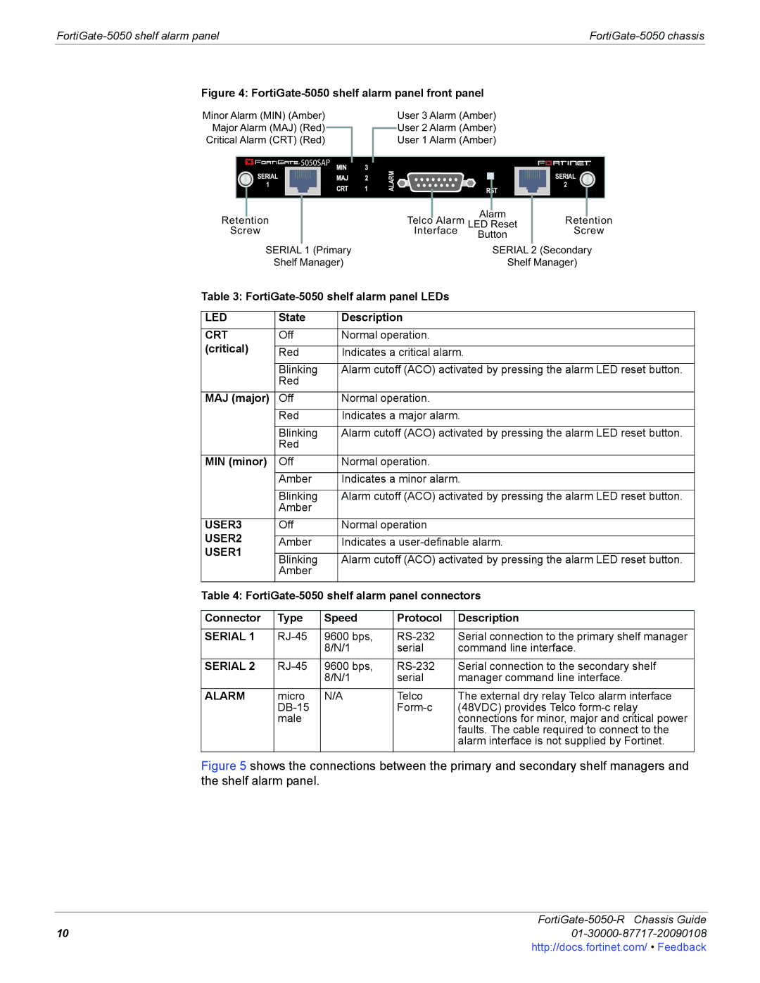
Figure 4: FortiGate-5050 shelf alarm panel front panel
Minor Alarm (MIN) (Amber)
Major Alarm (MAJ) (Red)
Critical Alarm (CRT) (Red)
![]()
![]() 5050SAP
5050SAP
SERIAL
1
Retention
Screw
SERIAL 1 (Primary
Shelf Manager)
User 3 Alarm (Amber)
User 2 Alarm (Amber)
User 1 Alarm (Amber)
|
|
|
|
|
|
|
|
| SERIAL |
| |
|
|
|
|
|
|
|
|
|
| ||
|
|
|
|
|
|
|
|
|
| ||
|
|
|
|
|
|
|
|
| 2 |
|
|
ALARM |
|
|
|
|
|
|
|
| |||
|
|
|
|
|
|
|
|
|
|
| |
|
|
|
|
| Alarm |
|
|
|
| ||
| Telco | Alarm | LED Reset |
| Retention | ||||||
|
| Interface | Button |
| Screw | ||||||
|
|
|
|
|
|
|
|
| |||
|
|
|
|
|
| SERIAL | 2 (Secondary | ||||
|
|
|
|
|
| Shelf Manager) | |||||
Table 3: |
| ||||
|
|
|
|
|
|
LED | State |
| Description |
| |
|
|
|
|
|
|
CRT | Off |
| Normal operation. |
| |
(critical) |
|
|
|
|
|
Red |
| Indicates a critical alarm. | |||
|
|
|
|
|
|
| Blinking |
| Alarm cutoff (ACO) activated by pressing the alarm LED reset button. | ||
| Red |
|
|
|
|
|
|
|
|
|
|
MAJ (major) | Off |
| Normal operation. |
| |
| Red |
| Indicates a major alarm. | ||
|
|
|
|
|
|
| Blinking |
| Alarm cutoff (ACO) activated by pressing the alarm LED reset button. | ||
| Red |
|
|
|
|
|
|
|
|
|
|
MIN (minor) | Off |
| Normal operation. |
| |
| Amber |
| Indicates a minor alarm. | ||
|
|
|
|
|
|
| Blinking |
| Alarm cutoff (ACO) activated by pressing the alarm LED reset button. | ||
| Amber |
|
|
|
|
|
|
|
|
|
|
USER3 | Off |
| Normal operation |
| |
USER2 |
|
|
|
|
|
Amber |
| Indicates a | |||
USER1 |
|
|
|
|
|
Blinking |
| Alarm cutoff (ACO) activated by pressing the alarm LED reset button. | |||
| Amber |
|
|
|
|
|
|
|
|
|
|
Table 4: | |||||
|
|
|
|
| |
Connector | Type | Speed | Protocol | Description | |
|
|
|
|
| |
SERIAL 1 | 9600 bps, | Serial connection to the primary shelf manager | |||
|
| 8/N/1 | serial | command line interface. | |
SERIAL 2 | 9600 bps, | Serial connection to the secondary shelf | |||
|
| 8/N/1 | serial | manager command line interface. | |
ALARM | micro | N/A | Telco | The external dry relay Telco alarm interface | |
|
|
| (48VDC) provides Telco | ||
| male |
|
|
| connections for minor, major and critical power |
|
|
|
|
| faults. The cable required to connect to the |
|
|
|
|
| alarm interface is not supplied by Fortinet. |
Figure 5 shows the connections between the primary and secondary shelf managers and the shelf alarm panel.
FortiGate-5050-R Chassis Guide
1001-30000-87717-20090108http://docs.fortinet.com/ • Feedback