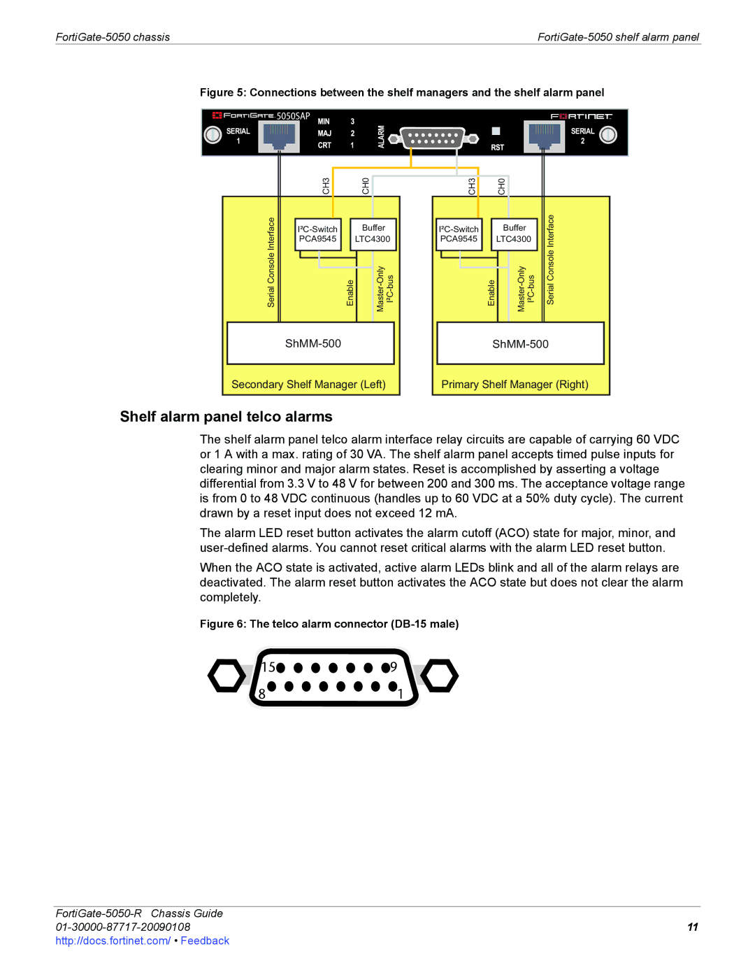
Figure 5: Connections between the shelf managers and the shelf alarm panel


 5050SAP
SERIAL
1
ALARM![]()
![]()
![]()
SERIAL
2
ConsoleSerialInterface | CH3 |
| CH0 |
|
Enable | ||||
|
| Buffer |
| |
| PCA9545 |
| LTC4300 | |
Secondary Shelf Manager (Left)
|
| CH3 |
|
|
| CH0 |
|
|
|
|
|
|
|
|
|
|
|
|
| ||
|
|
|
|
|
|
|
|
| ConsoleSerialInterface | |
| Enable |
| ||||||||
|
|
| Buffer |
|
|
| ||||
| PCA9545 |
|
| LTC4300 |
|
| ||||
|
|
|
|
|
|
|
|
|
|
|
Primary Shelf Manager (Right)
Shelf alarm panel telco alarms
The shelf alarm panel telco alarm interface relay circuits are capable of carrying 60 VDC or 1 A with a max. rating of 30 VA. The shelf alarm panel accepts timed pulse inputs for clearing minor and major alarm states. Reset is accomplished by asserting a voltage differential from 3.3 V to 48 V for between 200 and 300 ms. The acceptance voltage range is from 0 to 48 VDC continuous (handles up to 60 VDC at a 50% duty cycle). The current drawn by a reset input does not exceed 12 mA.
The alarm LED reset button activates the alarm cutoff (ACO) state for major, minor, and
When the ACO state is activated, active alarm LEDs blink and all of the alarm relays are deactivated. The alarm reset button activates the ACO state but does not clear the alarm completely.
Figure 6: The telco alarm connector (DB-15 male)
![]() 15
15![]()
![]()
![]()
![]()
![]()
![]()
![]() 9
9
81
| |
11 | |
http://docs.fortinet.com/ • Feedback |
|