FortiGate-5050 front panel
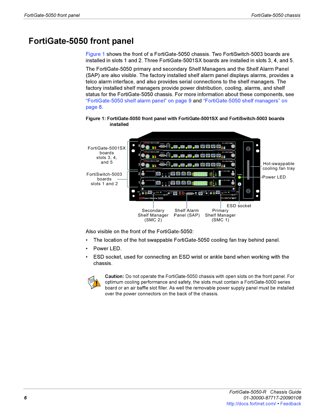
Figure 1 shows the front of a FortiGate-5050 chassis. Two FortiSwitch-5003 boards are installed in slots 1 and 2. Three FortiGate-5001SX boards are installed in slots 3, 4, and 5.
The FortiGate-5050 primary and secondary Shelf Managers and the Shelf Alarm Panel (SAP) are also visible. The factory installed shelf alarm panel displays alarms, provides a telco alarm interface, and also provides serial connections to the shelf managers. The factory installed shelf managers provide power distribution, cooling, alarms, and shelf status for the FortiGate-5050 chassis. For more information about these components, see “FortiGate-5050 shelf alarm panel” on page 9 and “FortiGate-5050 shelf managers” on page 8.
Figure 1: FortiGate-5050 front panel with FortiGate-5001SX and FortiSwitch-5003 boards installed
boards
slots 3, 4,
and 5
boards
slots 1 and 2
5 | CONSOLE | USB | 1 | 2 | 3 | 4 | 5 | 6 | 7 | 8 |
|
PWR ACC |
|
|
|
|
|
|
|
| STA | IPM |
4 | CONSOLE | USB | 1 | 2 | 3 | 4 | 5 | 6 | 7 | 8 |
|
PWR ACC |
|
|
|
|
|
|
|
| STA | IPM |
3 |
| CONSOLE | USB |
| 1 | 2 | 3 |
|
| 4 |
|
|
| 5 |
|
| 6 |
|
| 7 |
| 8 | |
PWR ACC |
|
|
|
|
|
|
|
|
|
|
|
|
|
|
|
|
|
|
|
| STA IPM | ||
| MANAGEMENT | TE H O |
| SR 2 3 2 | Z R E 0 | Z R E 1 | Z R E 2 |
|
|
|
|
|
|
|
|
|
| CLK OK | EXT INT FLT FLT | HOT SWAP |
|
| cooling fan tray |
2 | SYSTEM CONSOLE | E2 E1 | 14 15 | 12 13 | 10 11 | 8 9 | 6 7 | 4 5 | 2 3 | 0 1 | ZRE | RESET | LEDMODE | POWER | |||||||||
|
|
|
|
|
|
|
|
|
|
|
|
|
|
|
|
|
|
|
|
|
|
| Power LED |
1 | MANAGEMENT | ET H O | SYSTEM | CONSOLE | RS 2 3 2 | RZ E 0 | RZ E 1 | RZ E 2 | E2 E1 | 14 15 | 12 13 | 10 11 | 8 9 | 6 7 | 4 5 | 2 3 | 0 1 | ZRE | CLK OK | EXT INT FLT FLT | SWAPHOT | RESET | LED MODE |
SMC
2
5000SM
ETH1 | link/Act |
ETH0 | 10/100 |
link/Act | |
| 10/100 |
Service
ETH0
| STATUS | Hot Swap |
| 5050SAP |
| 5000SM | ETH0 | Service |
| STATUS | Hot Swap | SMC | |
|
|
| ETH0 ETH1 | 10/100 |
| ||||||||
RESET | SERIAL | ALARM | SERIAL | link/Act | RESET | ||||||||
10/100 | 1 | ||||||||||||
1 | 2 | link/Act | |||||||||||
|
|
|
|
|
|
|
|
|
|
|
|
| |
Secondary |
| ESD socket |
Shelf Alarm | Primary | |
Shelf Manager | Panel (SAP) | Shelf Manager |
(SMC 2) |
| (SMC 1) |
Also visible on the front of the
•The location of the hot swappable
•Power LED.
•ESD socket, used for connecting an ESD wrist or ankle band when working with the chassis.
Caution: Do not operate the
FortiGate-5050-R Chassis Guide
601-30000-87717-20090108http://docs.fortinet.com/ • Feedback