WIRING: 9-PIN Connector
Green: MODE A: |
|
|
|
|
|
|
|
|
|
|
|
|
|
|
|
|
|
|
|
|
|
|
|
|
|
|
|
|
|
| |
This wire allows an outside source or accessory to |
|
|
|
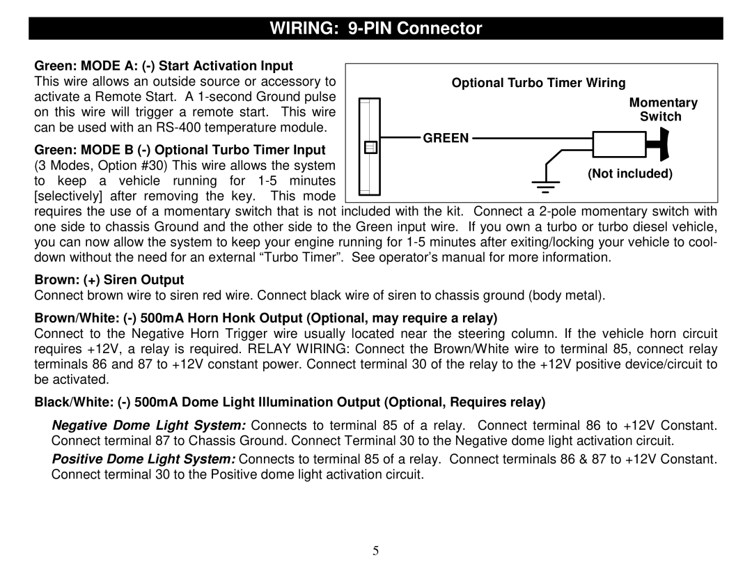
| Optional Turbo Timer Wiring | ||||||||||
activate a Remote Start. A |
|
|
|
|
|
|
|
|
|
|
|
| Momentary | ||
|
|
|
|
|
|
|
|
|
|
|
| ||||
on this wire will trigger a remote start. This wire |
|
|
|
|
|
|
|
|
|
|
|
| |||
|
|
|
|
|
|
|
|
|
|
|
| Switch | |||
can be used with an |
|
|
|
|
|
|
|
|
|
|
|
| |||
|
|
|
| GREEN |
|
|
|
|
|
|
|
|
|
| |
Green: MODE B |
|
|
|
|
|
|
|
| |||||||
|
|
|
|
|
|
|
| ||||||||
|
|
|
|
|
|
|
|
|
|
|
|
|
|
| |
|
|
|
|
|
|
|
|
|
|
|
|
|
|
| |
|
|
|
|
|
|
|
|
|
|
|
|
|
|
| |
(3 Modes, Option #30) This wire allows the system |
|
|
|
|
|
|
|
|
|
|
| (Not included) | |||
to keep a vehicle running for |
|
|
|
|
|
|
|
|
|
|
| ||||
|
|
|
|
|
|
|
|
|
|
|
|
|
|
| |
[selectively] after removing the key. This mode |
|
|
|
|
|
|
|
|
|
|
|
|
|
|
|
|
|
|
|
|
|
|
|
|
|
|
|
|
|
| |
|
|
|
|
|
|
|
|
|
|
|
|
|
|
| |
|
|
|
|
|
|
|
|
|
|
|
|
|
|
| |
requires the use of a momentary switch that is not included with the kit. Connect a
Brown: (+) Siren Output
Connect brown wire to siren red wire. Connect black wire of siren to chassis ground (body metal).
Brown/White:
Connect to the Negative Horn Trigger wire usually located near the steering column. If the vehicle horn circuit requires +12V, a relay is required. RELAY WIRING: Connect the Brown/White wire to terminal 85, connect relay terminals 86 and 87 to +12V constant power. Connect terminal 30 of the relay to the +12V positive device/circuit to be activated.
Black/White:
Negative Dome Light System: Connects to terminal 85 of a relay. Connect terminal 86 to +12V Constant. Connect terminal 87 to Chassis Ground. Connect Terminal 30 to the Negative dome light activation circuit.
Positive Dome Light System: Connects to terminal 85 of a relay. Connect terminals 86 & 87 to +12V Constant. Connect terminal 30 to the Positive dome light activation circuit.
5