Digital Multitracker
Safety Instructions
Precautions
Want to make a backup of song data
Want to save or load the mixing setting
Want to record my performance
Want to copy a part of a song to another track
Want to record a material while monitoring Input signal
Want to install the optional CD-RW/CD-R drive
Want to know details about the training mode
Want to know details about the mastering mode
Contents
Loop Function Setting the start and end points
Training mode
Mastering mode
Variable Pitch
102
122
124
125
Basic Features ofVF80
Product Features
Before Operating
Additional track
Trim
Names and Functions
Input A/UNBAL Unbalanced connector
Input A/BAL Balanced connector
Input B/UNBAL Unbalanced connector
Input B/BAL Balanced connector
Foot SW Foot switch connector
Peak indicators
CH ON/OFF keys
Track STATUS/TRACK SEL keys
Top panel Recorder/Display section
Contrast adjusting knob
Access indicator
Phantom indicator
Track Edit / PGM key
Setup / F1 key
Wave Form Scrub key
Vari Pitch / Edit key
Loop / Edit key
Rear panel
Side panel
Press the Setup key
Reformatting the hard disk
Press the ENTER/YES key while IDE is flashed
Turn on the VF80
Press the ENTER/YES key while the Record key is depressed
Replacing a hard disk
Operation Confirmed HD List for the VF80
Unscrew the four screws from the bottom of the main
Unit that are fixing the panel Is fixing the hard disk
Formatting the Hard disk
About a demonstration song
To check whether a demonstration song is recorded or not
Connections of external equipment
Sequencer
Disk remain indication
Switching the time base
Display when turning on the power
Preliminary knowledge
Balanced XLR and unbalanced phone input connectors
PHANTOMswitch
Basic recording recording onto a single track
Preparation for recording
Raise both the track 1 fader and master fader to0po- sition
Press the Record key
Undo/Redo
Recording
Playback
Basic recording recording onto two tracks
Stereo source
Spectively Press the Track STATUS/TRACK SEL keys ofTracks 3
To 0 position
See page 56 Recorder functions
How to use recording tracks effectively
Unarming tracks
Setting a mark on the fly
Mark function
Locating a mark
Deleting a mark
Punch in/out
Punch in/out using the foot switch
ABS locate functions
Auto punch in/out function
Rehearsal
Hint
Taking a mark point in the punch in or punch out point
Press the Auto Punch /EDIT key to illuminate the key
Adjusting levels
Adjusting EQ
Setting pan position
Mixing
Setting effects
Analog mixdown
Mixdown
Digital mixdown
Initial condition when turning on the power
Operations while the Normal screen is shown
Fader
Track mute
Adjusting pan positions
Use the JOG dial to adjust the pan position
After completing pan setting, press the EXIT/NO key
Mix parameter section
Editing EQ
Preset entries in the EQ library
L00 2-SHLV
Tips Low shelving type
High shelving type
LPF Low pass filter
HPF High pass filter
About A.S.P.+
Setting Effects
About Loop effect and Insert effect
How to make the loop effect setting
Reverb
Setting effect send levels
Use the JOG dial to adjust the send level value
Selecting an effect type
Selecting Pre/Post of the effect send
Use the JOG dial to select the desired effect type
Press the ENTER/YES key after selecting the effect type
To turn off the effect processor
Turning the effect processor on or off
To turn on the effect processor
About the effect types
Effect parameter details
Delay pitch effect parameters parameter type Delay Pitch
Chorus effect parameters parameter type Chorus
Flanger effect parameters parameter type Flange
Mono pitch effect parameters parameter type Mono Pitch
Scene memory
Storing the current scene
Recalling a scene
Hint
Fader adjust
Deleting a scene
Scene sequence
After selecting the scene number, press the ENTER/ YES key
Deleting a mark from the mark map
Scene sequence on/off selection
Executing the scene sequence
While theVF80 is stopped, press the Scene SEQ key
Cueing
Press the F FWD or Rewind key during playback
To return to the normal playback, press the Play key
VF80 is cueing in the forward direction
Performing digital scrubbing
Digital scrubbing
Storing the digital scrub point
Press the EXIT/NO key to return to the Normal screen
Vari Pitch
Press the Vari PITCH/EDIT key
Setting the Start and End points
Loop Function
Capturing the current position on-the-fly
Editing the position via the screen
Setting the Start and End points by marks
Carrying out the loop playback
Program
Creating a new program
Press the ENTER/YES key after entering the title
Press the EXIT/NO or Stop key
Editing a program title
Selecting a program
Deleting a program
Track editing
Copy & Paste
Move & Paste
Press the ENTER/YES key after editing/entering the title
Performing Copy or Move & Paste
Press the Time Base SEL key
Undo/redo of Copy & Paste
To set editing points by marks
Erasing track data
Erasing
Undo/redo of Erase
Track Exchange
Performing the track exchange
Use the JOG dial to select the source tracks
Tion tracks
Editing a mark position
Editing Marks
Viewing the mark list
Enter a mark title
Adding a mark
SETUP/F1 key while holding down the Shift key
Deleting a mark
Locating a mark
UNDO/REDO/F3 key while holding down the Shift key
Setting the tempo map
Setting the metronome output
Setting the time base to bar/beat
Metronome function
On/off of bounce mode
Setting pan positions
Setting level of each track
Track bounce Ping-pong recording
Press the Training key
Training mode
On/Off of training mode
Setting the cancel position
Canceling the center-positioned sound
Slowing down the playback speed
Changing the pitch
Mastering mode
On/off of mastering mode
Selecting a program to be played back
Press the Mastering key
Setting the mastering parameters
On/off of the mastering processing
Recording onto the master recorder
Mastering library details
L3 Live Mix
Newly added internal mastering function
Conventional mastering mode
Internal Mastering Function
Necessary
Screen for adjusting the mastering effects
Select the desired program for mastering
Punch- in function
When completing mastering, press the Stop Key to stop
Gram
About Start and End points
Press the Track EDIT/PGM key while VF80 is stopped
Press the ENTER/YES key
Mode
Using the insert effect
How to use the loop effect How to use the insert effect
Effect types available for the insert effect
Track bounce
Rehearsal
Raise the track 1 fader and Master fader to 0 position
Press the Record key
Press the Track STATUS/TRACK SEL key for
How to edit parameters
Storing parameter settings
Recording the guitar
Press the Stop key to stop recording
Press the BOUNCE/REC EFF key
Rerecording with effect
Press the Effect key
Name Comment
Parameters for distortion effects
Details of each distortion type
Details of each amplifier types
Details of microphone output types
Digital recording
Recording an external source onto the VF80 digitally
Midi clock sync system
Connecting external equipment
Connector
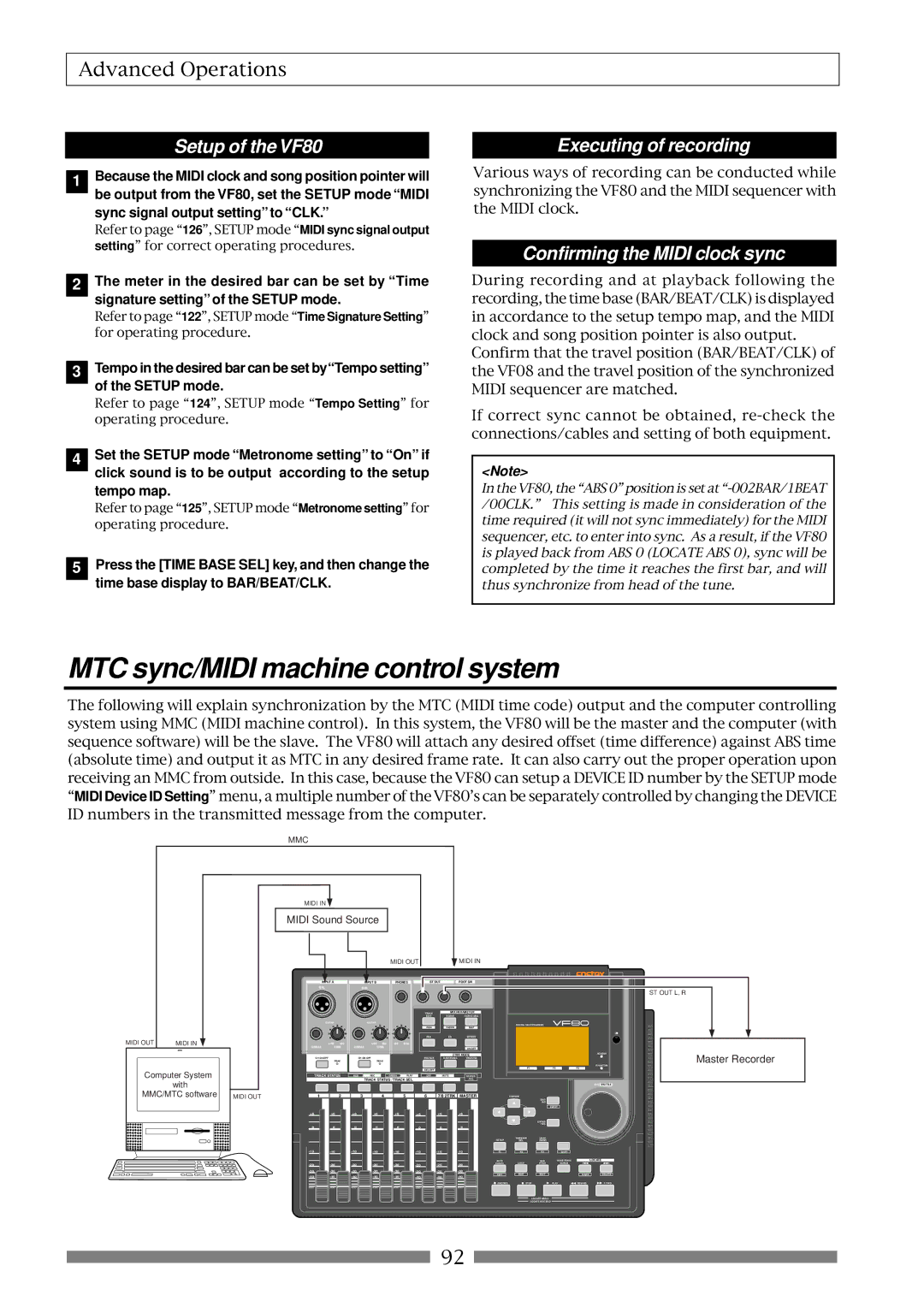
Setup of the VF80
Sync signal output setting to CLK
MTC sync/MIDI machine control system
Executing of recording
Connecting to external equipment
Setup of external equipment
Confirming MTC sync/MMC
Execution of recording
Confirming chase lock
External Midi equipment sync system by the slave mode
Connection to external equipment
Precautions at MTC related setups
One Point Advice
Offset mode For ABS
Offset mode For BAR/BEAT
Save/Load of song data
About song data
Setup mode
Items that can be saved or loaded as song data
Items that cannot be saved or loaded as song data
Memory data
Saving data using the S/PDIF digital signal
Connecting to an external digital recorder
Setting the external recorder
Saving data
Use the JOG dial to select the program to be saved
After checking all preparations on the external
Recorder are made, start it recording
Press the ENTER/YES key immediately after
Loading data
Loading data using the S/PDIF signal
Connecting to an external recorder
Start playback of the external recorder
Select tracks to be loaded
After selecting tracks, press the ENTER/YES key again
Stop the external recorder
Save/Load using CD-RW/CD-R
Care and handling of CD-RW/CD-R discs
About data writing and reading speeds for data save/load
Saving data using a CD-RW drive Backup
While BkUp flashing, press the ENTER/YES key
While IDE is flashing, press the ENTER/YES key
After selecting a program, press the ENTER/YES key
About save error
Hint
To erase the existing recorded data
While B01 is shown, press the ENTER/YES key
To eject the disc
Loading backup data from a CD-RW drive
While BkUp is flashing, press the ENTER/YES key
About load error
While New PGM is shown, press the ENTER/YES key
About directory of a backup disk
Saving a WAV file
About file names of WAV files
While WAV is flashing, press the ENTER/YES key
While Off is blinking, press the ENTER/YES key
After selecting the tracks, press the ENTER/YES key
To specify the desired tracks to From ** To
Showing the title and New File
After entering the file name, press the ENTER/YES key
Showing the title and -****MB
After selecting a file, press the ENTER/YES key
About WAV files saved
WAV file structure
WAV file structure which is saved over more than one disk
WAV file size
After selecting the desired WAV file, press
Loading a WAV file
Use the JOG dial to select Load PGM and press ENTER/YES key
Alphabets A-z Numerals Symbols #$%&’@‘=
Method to load specific tracks
Making an audio CD
Basic information
Press the ENTER/YES key while Scsi flashes
VF80
Copy protection setting
WhileCD-DA is flashing, press the ENTER/YES key
Start point = End point Start point End point
Press the ENTER/YES key again
If you erase recorded data
Press the ENTER/YES key while Erase and Sure? are flashing
Loading from an audio CD
Press the ENTER/YES key while IDE flashes
CD-RW/CD-R disc or commercially available audio CD
CD-DA
119
Press the EXIT/NO key to quit the Setup mode
Execution menu
Changing the initial settings menu
Check menu
JOG dial
To enter the Setup mode
Time signature setting Signature Set
Bar
Time
Setting a tempo Tempo Set
New Registering of Tempo
Track
Setting the Metronome function Click
Off default Metronome sound will not be output
Setting Midi sync output signal Midi Sync Out
Setting an MTC frame rate Frame Rate
Mtc
Off
Setting an MTC offset value Mtc Offset Set
Setting MTC Offset mode Offset Mode
Setting the Slave mode Slave Mode
Setting the SlaveType SlaveType
Vari
Setting the Record Protect function Rec Protect
Free
Setting Digital Input Digital
Setting BAR/BEAT Resolution mode Resolution
Setting the Midi device number Device ID
Checking the number of track events Number Of Event
Fader Fix Mode Setting Fader Fix
Drive Format Information Drive Information
Fader Recall Mode Setting Fader Recall
Press the EXIT/NO key or Stop key to exit from Setup mode
Initial setting
Master
Usable discs
CD-R discs
CD-RW discs
Audio CD discs
How to install the CD-1A
Insert the CD-1A unit to the VF80 as shown below
To open the tray, press the eject switch lightly
Opening/closing the tray
Placing/removing a disc
Place the disc with the label side up
Transmitted Recognized Remarks
Function
MMC Command List
Command list Movement Recorder
MMC Response/Information Field List Command
Inquiry Message List
Maintenance
Specifications
Recording/Reproducing
Input/Output
General
Block Diagram
Accessories
Block Diagram when using the insert effect
AD/C
Declaration of EC Directive
Page
Fostex Corporation